-
-
August 21, 2024 at 5:38 pm
l.v.lozovski
SubscriberHello,
I got some strange results when working with TFLN EOM, one of the files from the applications gallery (I modified it a little bit for my case). It worked fine for low voltage (below 5V), but when I apply a higher voltage something goes wrong. In your file it gives an erro when I try any voltage higher than 7V (Error: LN_phase_modulator_CHARGE.lsf line 41: in expression A(i,...) the index was out of range) and for my version of the file at some point n_eff increase becomes not linear with respect to voltage and even decreases further which I find very strange. Would you know what might be wrong? Thank you.
Kind regards,
Vadym
-
August 22, 2024 at 5:04 pm
Guilin Sun
Ansys EmployeeThis post raises two questions. Here are the answers:
1: Error: LN_phase_modulator_CHARGE.lsf line 41: in expression A(i,...) the index was out of range. If you did not modify the script, it should work. This error indicates size(E) might has something wrong. I modified the applied voltage and the script works fine:
2: "at some point n_eff increase becomes not linear with respect to voltage and even decreases further"
If the doping is strong and the applied voltage is too high, it may not keep linearity, and might be saturated. Please check the material properties /doping/vlotage and make sure they are physical.
-
August 22, 2024 at 7:05 pm
l.v.lozovski
SubscriberThanks for the reply
1) Yes I know what it says. But it just doesn't make sense...since it works with my configuration without giving errors. Yes I know that it works with 5V but I want to test it with larger voltage, or if it's not possible, at least know why...
2) There is no doping. It's Pockels effect.
-
August 22, 2024 at 7:06 pm
l.v.lozovski
SubscriberIs it possible to have a videocall to discuss it? Because there are other things that I find very strange in your software..
-
August 22, 2024 at 8:39 pm
Guilin Sun
Ansys EmployeeUnfortunately Forum does not have any other way of coomunications.
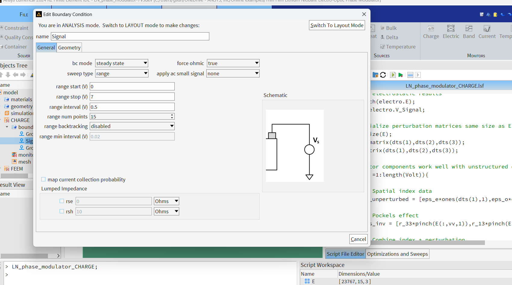
Please check that I used 7v while the online example is 5v. I am not sure what happened to your script. Please make sure you only changed the voltage max and number of steps, other than the material. You need to check the dimension of E and see what is wrong there.
?dts;
the 2nd dimension is the votage.
compare with the orginal file and find what is changed.
Please write a new post for any issues you have, preferably one post for one type of questions. This post has two different type of questions.
-
August 23, 2024 at 7:55 am
l.v.lozovski
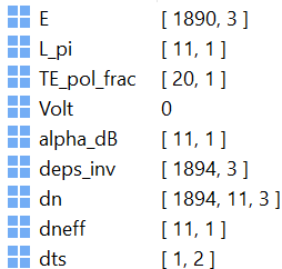
SubscriberWell I thought that you could tell me what is wrong, because the only thing I change is the voltage max (the step size changes automatically, I don't see why I should change the number of steps), but when I put Vmax = 10V one of the dimensions of the electric field disappears and looks like:

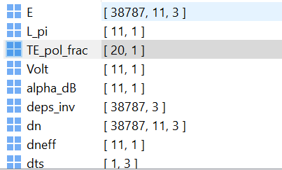
When actually it should look like this:

So my question is, why it does so?
-
August 23, 2024 at 3:01 pm
Guilin Sun
Ansys EmployeeI did not find how did you set the voltage so I cannot say what is wrong.
From your screnshot, it shows E does not record the voltage change. To dig it might be difficult. However, you can
1: download the online file and run it. make sure it runs without any issue.
2: then only change the voltage, run it and see if it works/
3: modify the materials and run
4: modify the structure if necessary and run
you need to isolate each test in order to find the root cause.
-
- You must be logged in to reply to this topic.


-
5014
-
1682
-
1387
-
1248
-
1021

© 2026 Copyright ANSYS, Inc. All rights reserved.


