TAGGED: -Ansys-Maxwell-electronics
-
-
November 12, 2024 at 12:05 pm
jjh4804a
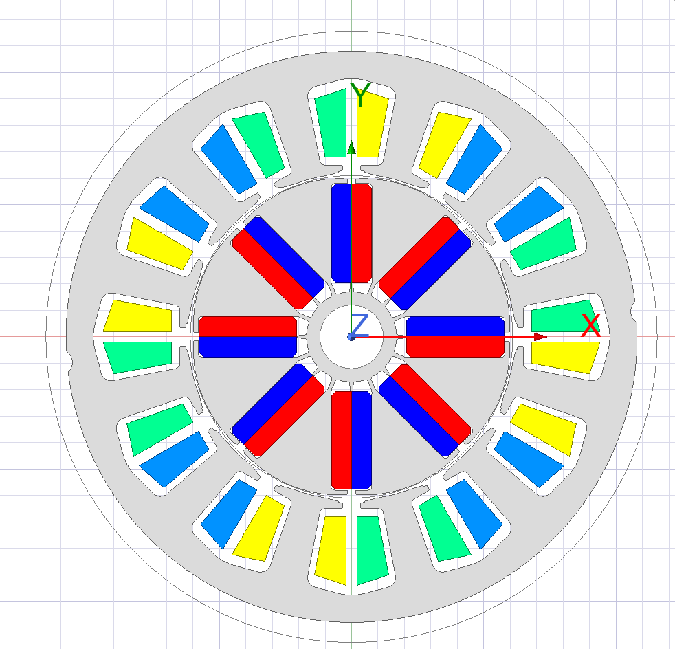
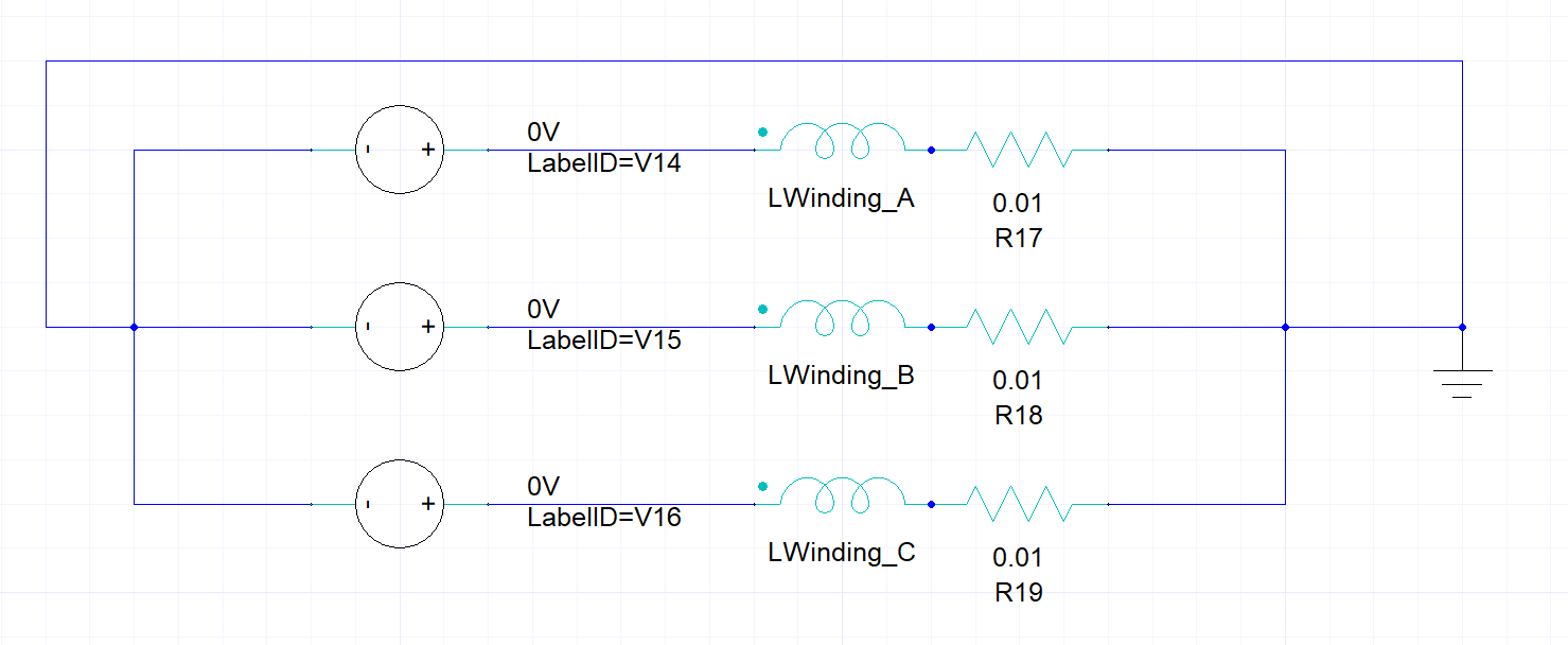
SubscriberI want to analyze a 12 slot 8 pole motor. I want to do it with a Y final, but I don't know how. I analyzed it by dividing it into Winding_A, B, and C as shown in the image below, but the back electromotive voltage waveform came out strangely. (The coils were divided into groups by the same color.) I want to first analyze the back electromotive voltage. Later, we plan to analyze torque, efficiency, voltage, and current.How can I modify the circuit diagram? If possible, please let me know with an image. Thank you. -
November 15, 2024 at 7:10 pm
GLUO
Ansys EmployeeHello,
For back EMF, you can use 0 current source to make the motor "open circuit", and measure the induced voltage.
GL
-
November 19, 2024 at 5:48 am
jjh4804a
SubscriberThe voltage is set to zero. Can you judge if there is a problem with the circuit diagram I made? I want to connect with a Y-line.
-
November 19, 2024 at 6:06 am
GLUO
Ansys EmployeeYou need to set current as 0, not voltage. Your circuit looks fine, if you have a connected neutral.
-
November 19, 2024 at 7:45 am
jjh4804a
SubscriberThe current was also set to 0.
When analyzed, the graph is not consistent and the desired value is not obtained. Is there a way to do Y wiring without using a circuit diagram?
When u, v, and w are grouped and interpreted, the graph is constant, but the back electromotive voltage value does not appear.
-
November 19, 2024 at 3:21 pm
GLUO
Ansys EmployeeYour circuit is already a Y connection with neutral. Without external circuit there is no connection inbetween windings, the excitations are only voltage or current applied on the windings. Back EMF is the induced voltage on windings in open loop condition, which is represented using 0 current. Please check other factors like magnet polarity.
-
November 20, 2024 at 12:39 am
jjh4804a
SubscriberIs it possible to make Y connection in the next setting?
Excitations>Setup Y Connection. -
November 20, 2024 at 12:47 am
GLUO
Ansys EmployeeThis feature does not support current source. User must use 0 amp current source for back EMF simulation.
-
November 20, 2024 at 7:09 am
jjh4804a
SubscriberThen, I wonder what kind of connection it will be if we interpret only the winding group as u,v,w without creating an external circuit.
-
-
-
- You must be logged in to reply to this topic.


-
4939
-
1639
-
1386
-
1242
-
1021

© 2026 Copyright ANSYS, Inc. All rights reserved.


