-
-
February 21, 2024 at 8:52 pm
wallybanger
SubscriberHey Guys, I've been following some tutorials and playing with the non-linear analysis settings and I can't seem to beat this convergance issue.
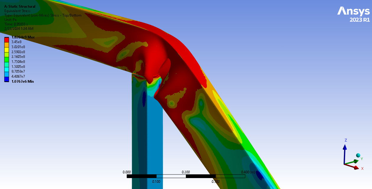
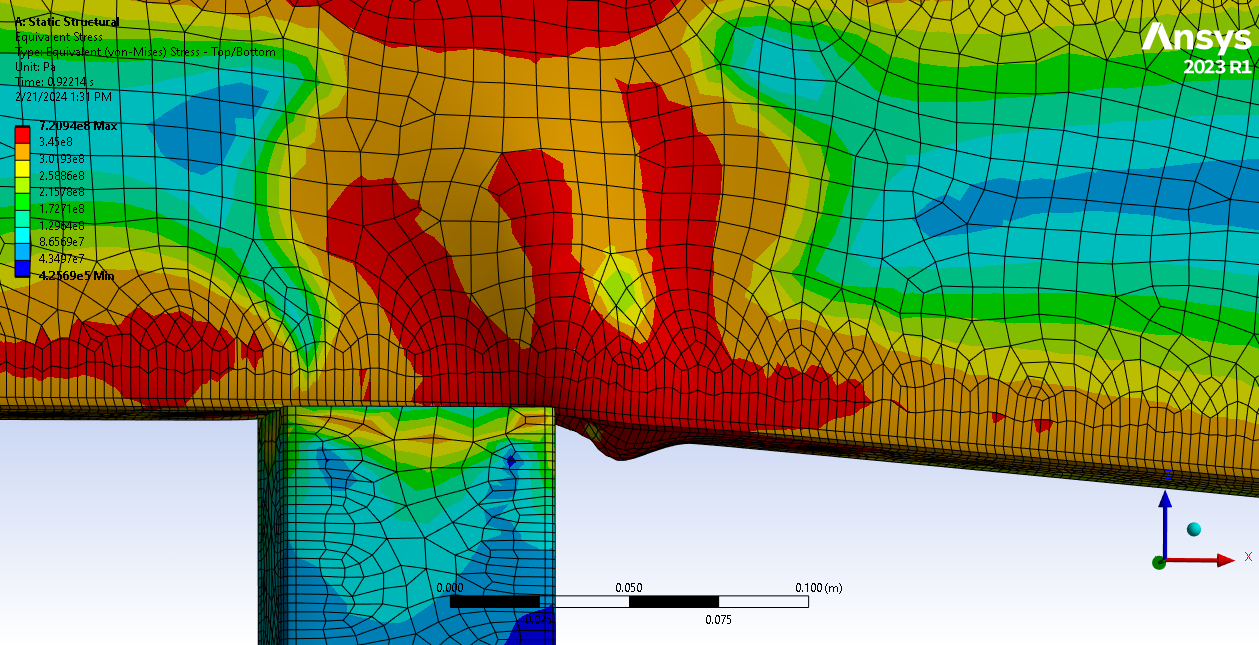
It's a 6"x2" beam on top of a 3"x3" post. All 14ga material @ 50ksi yeild.
I've been meshing it as an all quad mesh with a 10mm primary element size and a 2.5mm element size for the corner radii. It's meshed off of a surface with a 2mm thickness (.08" or 14ga).
I've applied a 60,000n force to the top edges.
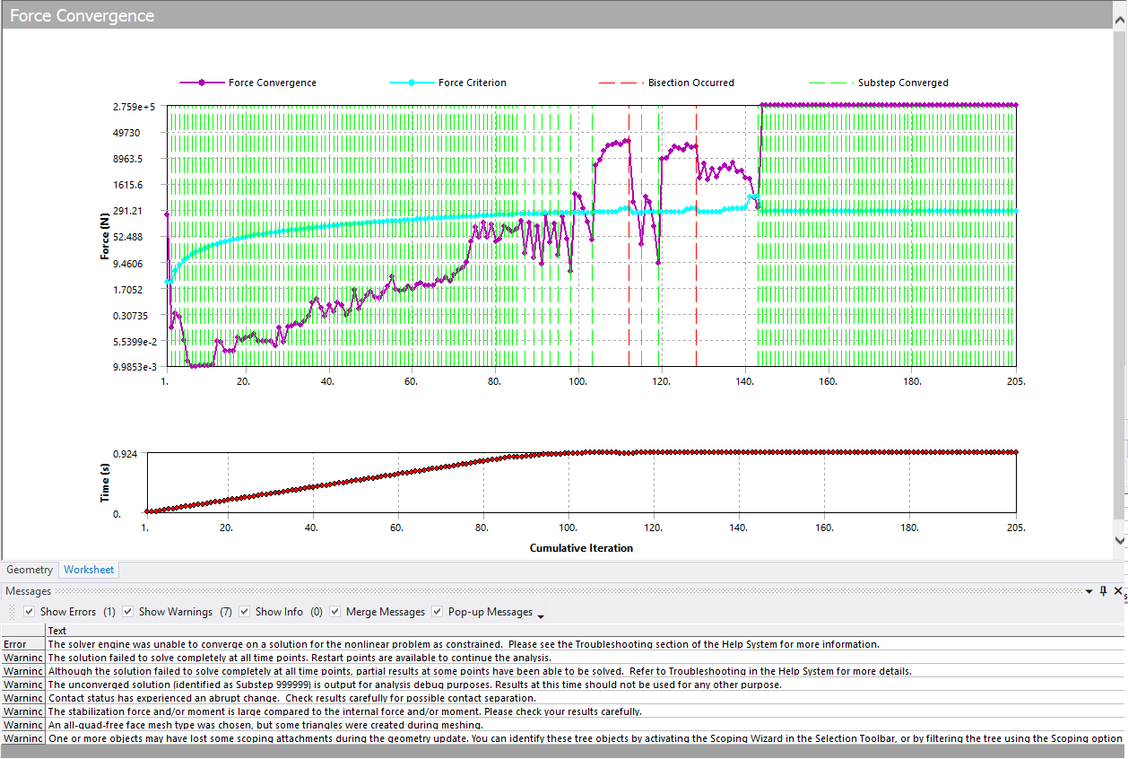
This is what the force convergance chart looks like
I was getting results like this but it was failing so I added in the SEMIIMPLICIT commandline in the APDL.
This is the error I get:
>>> SOLUTION CONVERGED AFTER EQUILIBRIUM ITERATION 15
*** WARNING *** CP = 3420.078 TIME= 13:12:27
For load step 1 substep 94, stabilization moment norm = 31.5757016 is
large compared to the internal moment norm 47.3393818. Please check
the result carefully.
*** LOAD STEP 1 SUBSTEP 94 COMPLETED. CUM ITER = 143
*** TIME = 0.922000 TIME INC = 0.400000E-02
*** MAX PLASTIC STRAIN STEP = 0.1816 CRITERION = 0.1500
*** AUTO STEP TIME: NEXT TIME INC = 0.40000E-02 UNCHANGED
FORCE CONVERGENCE VALUE = 0.2759E+06 CRITERION= 266.2
MOMENT CONVERGENCE VALUE = 1297. CRITERION= 0.2306
DISP CONVERGENCE VALUE = 0.1616E-01 CRITERION= 0.1629E-02
EQUIL ITER 1 COMPLETED. NEW TRIANG MATRIX. MAX DOF INC= -4.487
*** ERROR *** CP = 3430.438 TIME= 13:12:38
Element 104714 has excessive distortion.
*** WARNING *** CP = 3430.453 TIME= 13:12:38
Contact status (Real ID: 4) changes abruptly from in-contact to
far-field.
>>> TRANSITIONING TO SEMI-IMPLICIT METHOD
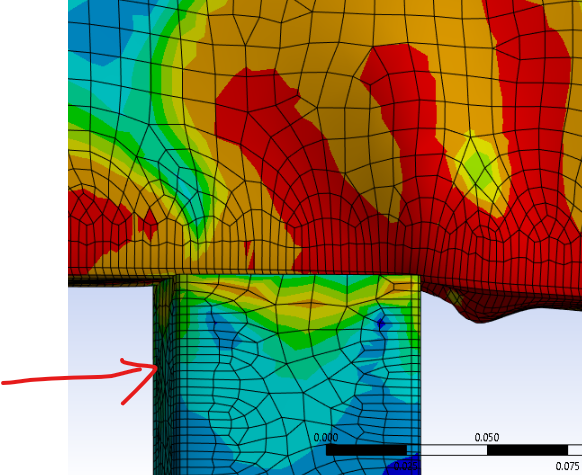
This is element 104714
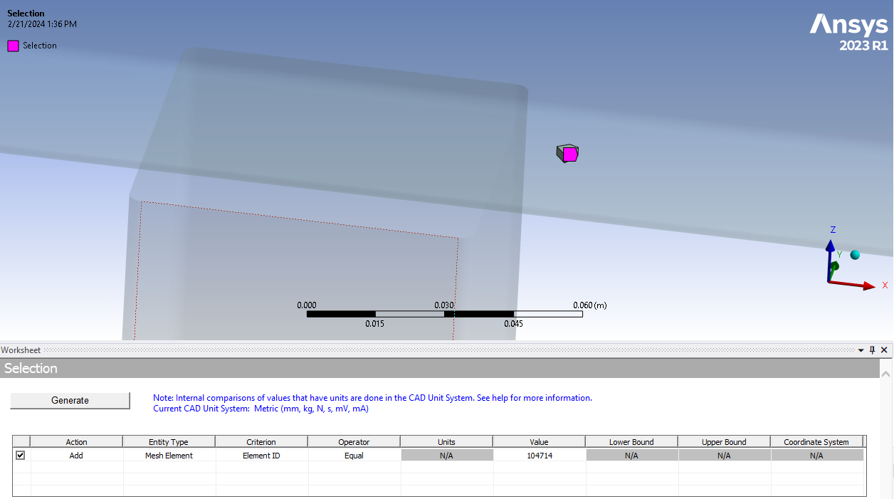
Now this all makes sense but I the question is, is there a way to allow the analysis to go further? I would like to see more buckling and then see the spring-back in a second step where the force is removed. So far the analysis fails before reaching step 2. I tried reducing the loading until it converges (about 55,000n) and I got the analysis to successfully move to step 2 but there is no buckling (Step 2 did fail but I think it's because I had it set to auto time stepping).
I have the time stepping set to 100 initial steps with 250 max. I did this because I didn't want the analysis going forever. It looks like it's failing because of excessive deformation anyway, not because I don't have enough time steps but I'm very open to opinions.
Thanks in advance
-
February 22, 2024 at 10:25 am
Ashish Khemka
Forum Moderator-
February 22, 2024 at 6:10 pm
wallybanger
SubscriberHi, thanks for the reply. I'm trying to figure out how to introduce self contact between the bodies but, so far, no luck. I do need the stress from the lower body... the lower body is actually the part I'm most concerned with but I'm kinda just playing around to see what the capabilites of the software are.
I remeshed the whole thing with a 2.5mm triangular mesh and got some really good results but the bodies pass through one another with large deformation. Is there a way to prevent the meshes from passing through one another? I tried a frictionless contact between the surfaces with the largest deformation but my analysis stalled out. This is the best I've been able to do so far:
-
-
February 23, 2024 at 6:21 am
Ashish Khemka
Forum ModeratorMike, by self contact I meant that define the bottom face of lower body as contact and the same surface as target, so that when the lower body bends it allows for face to come into contact.
Regards,
Ashish Khemka
-
February 23, 2024 at 5:42 pm
wallybanger
SubscriberI don't think I understand what you mean. So there is a post and a truss. The post is the vertical part. The truss is the horizontal part that is deflecting.
I can set up a contact between the bottom face of the truss and the forward face of the post where they would make contact with one another. Is that what you mean? I tried that. The analysis failed and didn't even give me results I could view. The bottom face of the truss is already being used in a bonded contact with the top of the post. Could that be causing the problem? Do I need to define a seperate face to use for the contact?
I was thinking that maybe it would be better to mesh the entire thing as a solid part as opposed to 2 parts but if you look at the truss you can see that the inside and outside faces are crossing through one another so ansys doesn't even know when a body mesh is self intersecting... which is insane.
How can I stop those meshes from passing through one another?
-
February 23, 2024 at 6:59 pm
wallybanger
SubscriberOK, I looked at the solver output and it definitely says it's failing because of too much penetration.
I understand completely how there can be penetration between 2 seperate bodies with no connections between them but how is a single part/mesh allowed to penetrate it's self? Is this because the solver switches to semi implicit?? Is there a setting I'm missing or something I need to change in the solver settings?
It ran more or less correctly for about 112 steps. The solver doesn't switch to semi implicit until step 111. I can see that mesh penetration starts at around step 105.
-
- The topic ‘Playing with Non-Linear Analysis’ is closed to new replies.
-
4924
-
1613
-
1386
-
1242
-
1021
© 2026 Copyright ANSYS, Inc. All rights reserved.


