-
-
October 3, 2023 at 8:47 pm
ZenerDalf
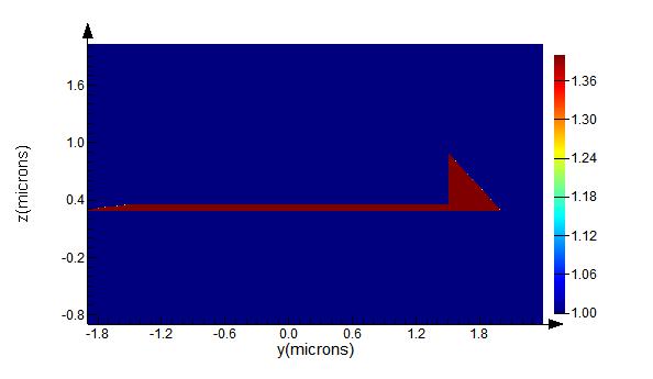
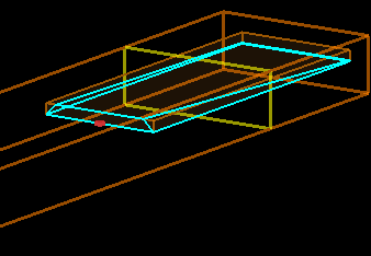
SubscriberI am currently trying to simulate a waveguide that has a vertical taper along with sidewall angles using the planar solid primitive. Once I run my script the waveguide looks to be correct but when the monitor is put at the input and output of the waveguide it seems to have some issues. Could someone lead me in the right direction?
Here is the script used:
y1=-1.5e-6-0.5e-6;
y2=-1.5e-6-0.5e-6;
y3=1.5e-6+0.5e-6;
y4=1.5e-6+0.5e-6;
y5=-1.5e-6;
y6=-1.5e-6;
y7=1.5e-6;
y8=1.5e-6;
z1=0;
z2=0;
z3=0;
z4=0;
z5=0.6e-6;
z6=0.06e-6;
z7=0.06e-6;
z8=0.6e-6;
vtx= [x1,y1,z1; #1
x2,y2,z2; #2
x3,y3,z3; #3
x4,y4,z4; #4
x5,y5,z5; #5
x6,y6,z6; #6
x7,y7,z7; #7
x8,y8,z8]; #8
a = cell(6);
for(i = 1:6){
a{i} = cell(1);
}
#facets:
a{1}{1} = [1,4,3,2]; #bottom facet
a{2}{1} = [1,2,6,5];
a{3}{1} = [2,3,7,6];
a{4}{1} = [3,4,8,7];
a{5}{1} = [1,5,8,4];
a{6}{1} = [5,6,7,8]; #top facet
addplanarsolid(vtx,a);
-
October 3, 2023 at 9:40 pm
Amrita Pati
Ansys EmployeeHi Lucio,
I can take a look at this. I believe you have left a portion of the script at the beginning where x1 through x8 are defined. Would you be able to share the full script? And also if you are using the script to setup the monitor, then please share that as well. If not, you can just share a screenshot of the geometry tab of the monitor. This would help me reproduce the issue and we can get to the root much sooner. Thank you!Regards,
Amrita-
October 3, 2023 at 11:37 pm
ZenerDalf
SubscriberHi Amrita,
thank you for the response. I accidentally did not include the x1 through x8.
I have posted below the full script:
deleteall; clear;
x1=0;
x2=10e-6;
x3=10e-6;
x4=0;
x5=0;
x6=10e-6;
x7=10e-6;
x8=0;y1=-1.5e-6-0.5e-6;
y2=-1.5e-6-0.5e-6;
y3=1.5e-6+0.5e-6;
y4=1.5e-6+0.5e-6;
y5=-1.5e-6;
y6=-1.5e-6;
y7=1.5e-6;
y8=1.5e-6;
z1=0;
z2=0;
z3=0;
z4=0;
z5=0.6e-6;
z6=0.06e-6;
z7=0.06e-6;
z8=0.6e-6;
vtx= [x1,y1,z1; #1
x2,y2,z2; #2
x3,y3,z3; #3
x4,y4,z4; #4
x5,y5,z5; #5
x6,y6,z6; #6
x7,y7,z7; #7
x8,y8,z8]; #8
a = cell(6);for(i = 1:6){
a{i} = cell(1);
}
#facets:
a{1}{1} = [1,4,3,2]; #bottom facet
a{2}{1} = [1,2,6,5];
a{3}{1} = [2,3,7,6];
a{4}{1} = [3,4,8,7];
a{5}{1} = [1,5,8,4];
a{6}{1} = [5,6,7,8]; #top facet
addplanarsolid(vtx,a);
set("index",4);
set("x",0);addmesh;
set("based on a structure",1);
set("structure","solid");
set("buffer",0e-6);
set("dy",0.001e-6);
set("dz",0.001e-6);
set("dx",0.001e-6);addfdtd;
set("x",0e-6);
set("x span",20e-6);
set("y",0);
set("y span",5e-6);
set("z",0);
set("z span",3e-6);addindex;
set("monitor type","2D X-normal");
set("x",10e-6);
set("y",0);
set("y span",8e-6);
set("z",0);
set("z span",8e-6);
addindex;
set("monitor type","2D X-normal");
set("x",0e-6);
set("y",0);
set("y span",8e-6);
set("z",0);
set("z span",8e-6);
-
-
October 4, 2023 at 4:44 pm
Amrita Pati
Ansys EmployeeHi Lucio,
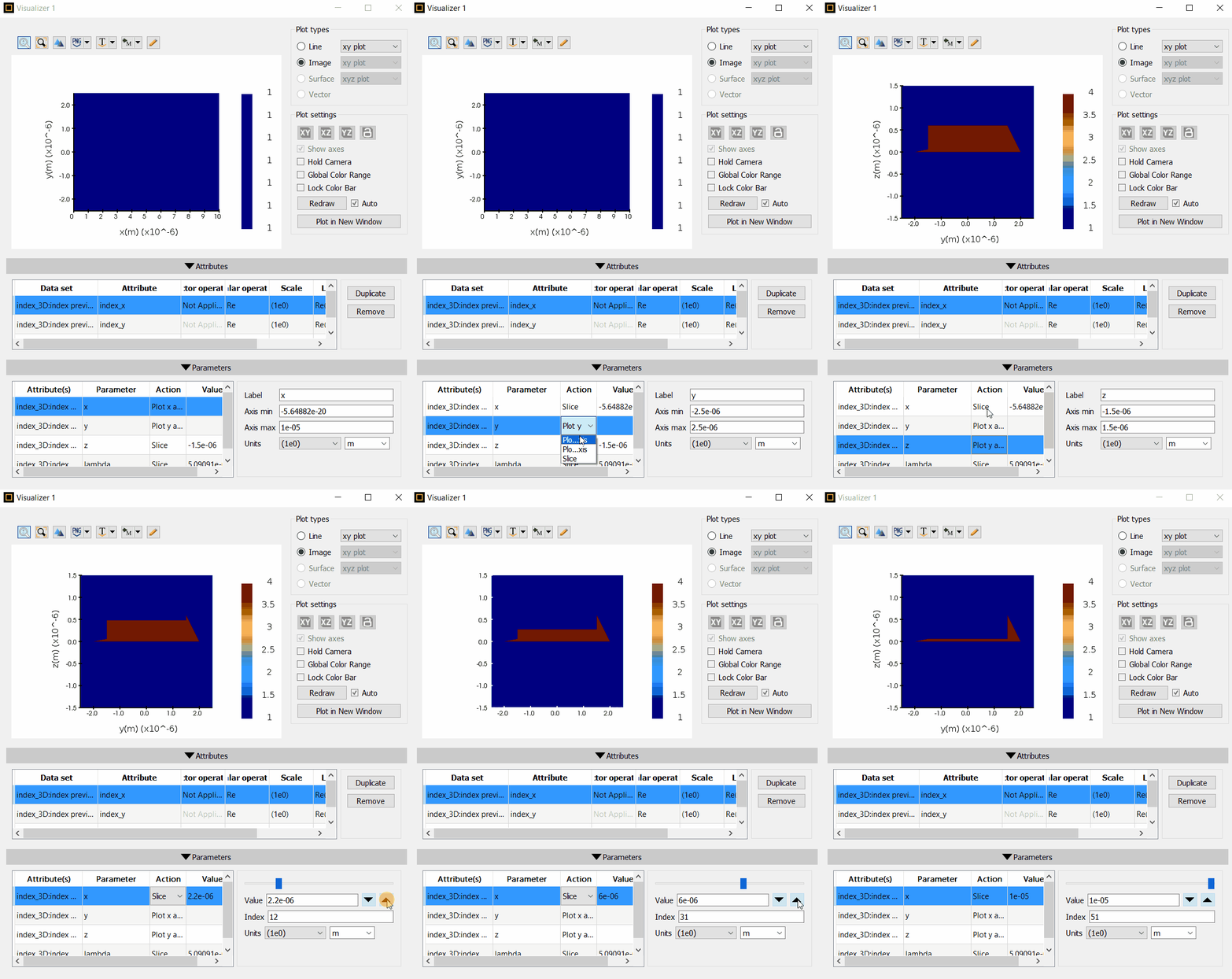
Thanks for sharing the code! I believe the solid has not been set up properly, and it is hard to visualize that in the GUI. I added a 3D index monitor, with down sampled X,Y,Z (to reduce memory requirements) and viewed the y-z planes of the index for different values of x.
Here is the code I used to set up the monitor:
addindex;
set("monitor type","3D");
set("name","index_3D");
set("x",5e-6);
set("x span",10e-6);
set("y",0);
set("y span",5e-6);
set("z",0);
set("z span",3e-6);
set("down sample X",200);
set("down sample Y",5);
set("down sample Z",5);
You can add it at the end of your code. The following GIF shows how you can view the y-z planes (x-Slice, y- Plot x axis and z- Plot y axis). As you can see this is not how the structure is supposed to look. I will take another look at the set up of the structure this afternoon and get back to you. I will also recommend you to have a secon look at the setup and make sure all the facets/coordinates are accurate.
Regards,
Amrita -
October 4, 2023 at 5:15 pm
ZenerDalf
SubscriberHi Anita,
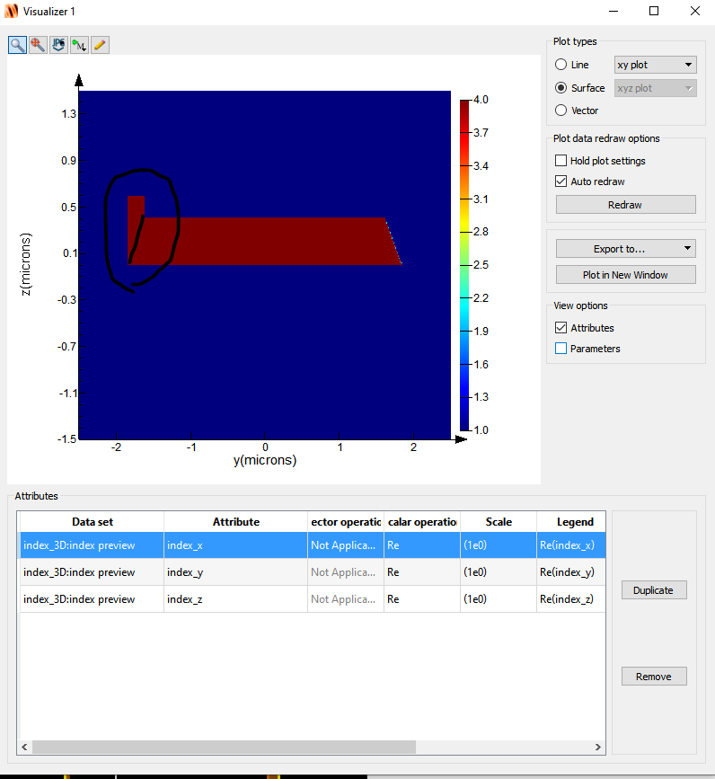
I reposted the code with the appropriate parameters as well as included an in image of the the 3d Index monitor. When looking at the lef hand side there seem to be a rectangle present. This should actually mirror what is shown on the right hand side of the index (a diagonal). This error is shown throughout all the slices as the x position is moved. It also shows up in the the gif you have uploaded. I have tried changing the parameters but wasn't able to figure out if there is an issue of how I've defined the planarsolid.
deleteall; clear;
x1=0;
x2=10e-6;
x3=10e-6;
x4=0;
x5=0;
x6=10e-6;
x7=10e-6;
x8=0;y1=-1.8464e-6;
y2=-1.8464e-6;
y3=1.8464e-6;
y4=1.8464e-6;
y5=-1.5e-6;
y6=-1.8464e-6;
y7=1.8464e-6;
y8=1.5e-6;z1=0;
z2=0;
z3=0;
z4=0;
z5=0.6e-6;
z6=0.05e-6;
z7=0.05e-6;
z8=0.6e-6;vtx= [x1,y1,z1; #1
x2,y2,z2; #2
x3,y3,z3; #3
x4,y4,z4; #4
x5,y5,z5; #5
x6,y6,z6; #6
x7,y7,z7; #7
x8,y8,z8]; #8
a = cell(6);
for(i = 1:6){
a{i} = cell(1);
}
#facets:a{1}{1} = [1,4,3,2]; #bottom facet
a{2}{1} = [1,2,6,5];
a{3}{1} = [2,3,7,6];
a{4}{1} = [3,4,8,7];
a{5}{1} = [1,5,8,4];
a{6}{1} = [5,6,7,8]; #top facetaddplanarsolid(vtx,a);
set("index",4);
set("x",0);
addmesh;
set("based on a structure",1);
set("structure","solid");
set("buffer",0e-6);
set("dy",0.001e-6);
set("dz",0.001e-6);
set("dx",0.001e-6);addfdtd;
set("x",0e-6);
set("x span",20e-6);
set("y",0);
set("y span",5e-6);
set("z",0);
set("z span",3e-6);addindex;
set("monitor type","3D");
set("name","index_3D");
set("x",5e-6);
set("x span",10e-6);
set("y",0);
set("y span",5e-6);
set("z",0);
set("z span",3e-6);
set("down sample X",200);
set("down sample Y",5);
set("down sample Z",5); -
October 4, 2023 at 5:34 pm
Amrita Pati
Ansys EmployeeHi Lucio,
Thanks for the additional information. I haven't actually had the chance to look at the set up itself. I was just trying to see if the set up is expected/reasonable or not. I know it can be a little tricky to create the planar solid. I will have a look at the setup parameters this afternoon and get back to you.
Regards,
Amrita -
October 4, 2023 at 10:09 pm
Amrita Pati
Ansys EmployeeHi Lucio,
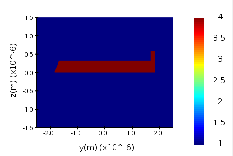
I ran a few more tests. The only point I would like to address with regard to the setup script is that you have defined the vertices of the facets in a clockwise direction. It should be defined in counter-clockwise manner (looking from outside the object) for a facet and clockwise direction for a hole in the facet. But making that change just shifts the rectangular protusion from left to right.
I checked the index with different types of mesh and different levels of accuracy but nothing seems to help. I also checked the rendering of the object in wireframe form and I do not see any issue with the visualization of the object itself.
I will pose this to the larger team including the R&D by the end of the day just to make sure that we haven't made any mistake with the setup. If it turns out to be a bug, I will submit a bug report and we can discuss if there are any alternatives.
Regards,
Amrita -
October 6, 2023 at 1:04 pm
ZenerDalf
SubscriberHi Amrita,
sounds good.
-Lucio
-
October 10, 2023 at 5:58 pm
Amrita Pati
Ansys EmployeeHi Lucio,
This most likely is a bug, so I have submitted a bug report. Let me think of how else we can generate the structure. Also, I will let you know if there are any updates regarding the bug itself.
Regards,
Amrita -
October 11, 2023 at 1:36 pm
ZenerDalf
SubscriberHi Amrita,
thank you for confirming that it is a bug!
Sincerely,
Lucio
-
October 18, 2023 at 8:17 pm
Amrita Pati
Ansys EmployeeHi Lucio,
I just heard back from the Development Team.
Here are their comments:
"Object does not render in the Modern viewport, which is a strong suggestion that there is something wrong with the geometry specification."
For example, the edge 6->2 is parallel the z-axis, and edge 2->1 is parallel the x-axis, but edge 1 ->5 is not in an XZ plane. The best option for you is to adjust vertices 6 and 7, and check with Modern viewport.
I haven't had the chance to test this myself but I will suggest you to try these recommendations. We also think that the geometry (or one or more of its facets) should be surrounded by a red box to indicate that a certain geometry (or facets) are problematic. This will help customers identify any issue with the geometry. I will submit this feature request.
Let me know if you have any questions.
Regards,
Amrita
-
- The topic ‘Planar Solid Not Working as Expected’ is closed to new replies.


-
4628
-
1535
-
1386
-
1215
-
1021

© 2025 Copyright ANSYS, Inc. All rights reserved.


