-
-
October 31, 2023 at 2:14 pm
Mahir
SubscriberHello,
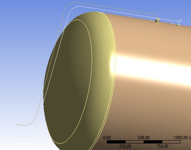
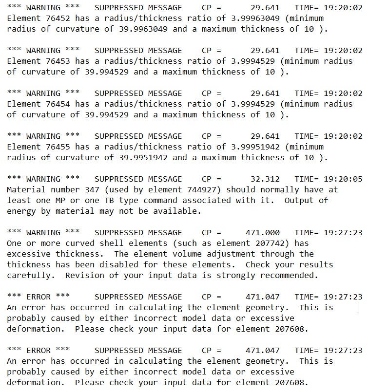
I have tank model as shell body, and there are pipes which are connected to tank. Pipes are modeled as a line body. As I watch some videos they are recommending to mesh Quadratic. I meshed all elements Qadratratic . Then with Pipe linerization i selected all elbows. factor is 2x.But I am alwas getting warningand simulation cant complete. All warning is the same, warning message is ''Element X has a radius/thickness ratio of 3.46 (minumum radius of curvatture of 30.150 and a maximum thickness of 8.7). What reasons can cause this problem and how can i fix ? if somebody help, i will be appreciate.
-
November 1, 2023 at 4:12 pm
Gary Stofan
Ansys EmployeeIt seems the radius is too sharp for the diameter of the pipe.
From the error message, we need to understand what the terms are''Element X has a radius/thickness ratio of 3.46 (minumum radius of curvature of 30.150 and a maximum thickness of 8.7)"
The Ansys Help file has a Pipe verification test that can help us understand the terms and their relations.
https://ansyshelp.ansys.com/account/secured?returnurl=/Views/Secured/corp/v232/en/ans_vm/vnmr_prob1.htmlProblem Description
A cantilevered bend pipe is modeled with a ratio of outer radius to wall thickness equal to 45.36....Outer diameter = 10.932 inches
Wall thickness = 0.1205 inches
Radius of curvature = 36.30 inches
So, plug your numbers into the realtion and see how you compare to a valid case. -
November 1, 2023 at 5:25 pm
Mahir
SubscriberHello Gary,
First of all, thank you so much for your response and your time. But what you mean about " plug your numbers into the realtion and see how you compare to a valid case.''
In my case for example one elbow has
Wall thickness = 5.1 mm, Outer diameter = 48.3 mm and radius of curvature= 170 mm. What should i do now ? -
November 1, 2023 at 6:12 pm
Gary Stofan
Ansys EmployeeI have a question
In your solver output Solution Information.What are the Errors that stop the solution (not Warnings)?
Gary
-
November 1, 2023 at 6:41 pm
-
November 1, 2023 at 6:54 pm
Gary Stofan
Ansys EmployeeHi. OK. It seems something is not constrained or elements are not connected.
Try a simple structural analysis with fixed supports and a gravity (or small acceleration load).
You might also try enabling Weak Springs in the Analysis settings. -
November 1, 2023 at 8:05 pm
mjmiddle
Ansys EmployeeI think the last two errors about "An error has occurred in calculating the element geometry" is basically the same thing as the previous error: "''Element X has a radius/thickness ratio..."
The 2D line idealization, whether it's a beam or pipe, usually depends on the length dimension being much more than the cross section dimensions. Along this idea, but not exactly the same, is the radius/thickness ratio should not be too small. If the bend radius is too small compared to maximum cross section dimensions, the cross sections intersect at the bend, and the formation is not physically possible if this were a solid body or a real physical model. When Gary said plug numbers into the equation earlier, he meant to compare your ratio to the ratio of a working example. Just divide the "radius of curvature" by the "Outer diameter" or in this case, the maximum cross section dimension is important when measured to the pipe idealzation line at the centroid of any cross section. So divide the diameter by 2 to use the radius. 36.3/(10.932/2) = 6.64.
But "a picture says a thousand words." To make this easy, just turn on cross section display. You can usuallty see right away if this is a problem:
-
November 10, 2023 at 8:08 am
Mahir
SubscriberHi, Thank you so much for help. When I check to cross section display. It seems all is okay. I think the issue was related with contacts. I solved to problem. Thank you for support
-
November 10, 2023 at 9:58 am
ErKo
Ansys EmployeeHi
That is good to hear - thanks for letting us know.
All the best
Erik
-
- The topic ‘Pipe Idealiziation Error’ is closed to new replies.


-
4708
-
1565
-
1386
-
1242
-
1021

© 2026 Copyright ANSYS, Inc. All rights reserved.


