
-
-
August 11, 2020 at 4:14 am
bittus
Subscriberi am analyzing a pin on disc test.
in the solution part pin deformation is coming more than disc. in reality this is not the case.
also in the eq stress part, only pin stress it is showing and not of disc.
August 11, 2020 at 3:14 pmSean Harvey
Ansys EmployeeHello,nLet's see if we can help out. I think what is happening is your revolute join of disc to pin. The revolute joint has only rotation about Z degree of freedom. If it is scoped on the pin, the pin won't translate in Z, assuming if you force is pushing in the Z direction. A cylindrical joint does have Z degree of freedom, so maybe you just need to change the joint from revolute to cylindrical. Can you try that? Thanks.nnSean HarveynAugust 12, 2020 at 5:05 amSubscriberHello,nnthank you for your response.nthe results are same, no changes are seen even after changing re volute to cylindrical. nALSO, To make myself clear i have selected stiffness behavior of disc as rigid and pin as flexible in geometry. nand top of pin is fixed, and there the force is being applied.nnkindly advice n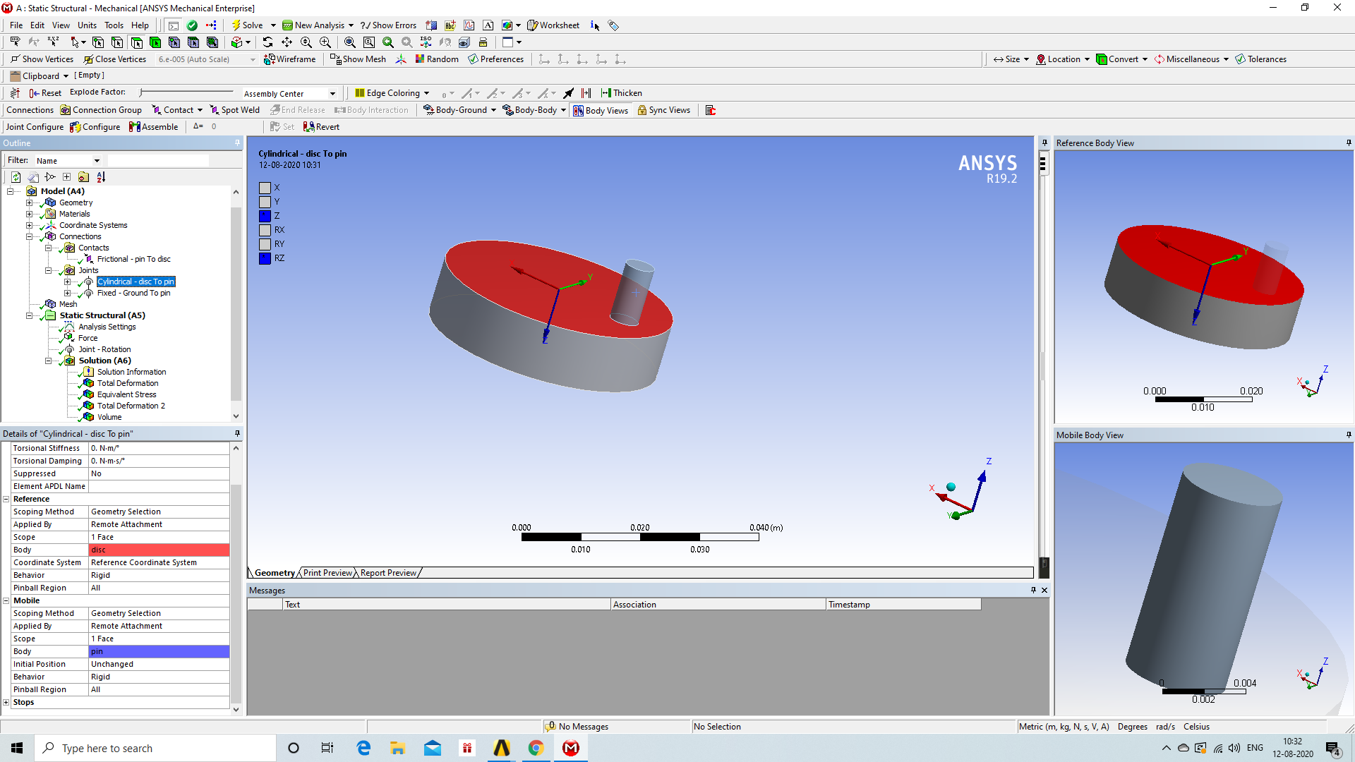 the model that i am trying to simulate roughly looks like thisn
 n
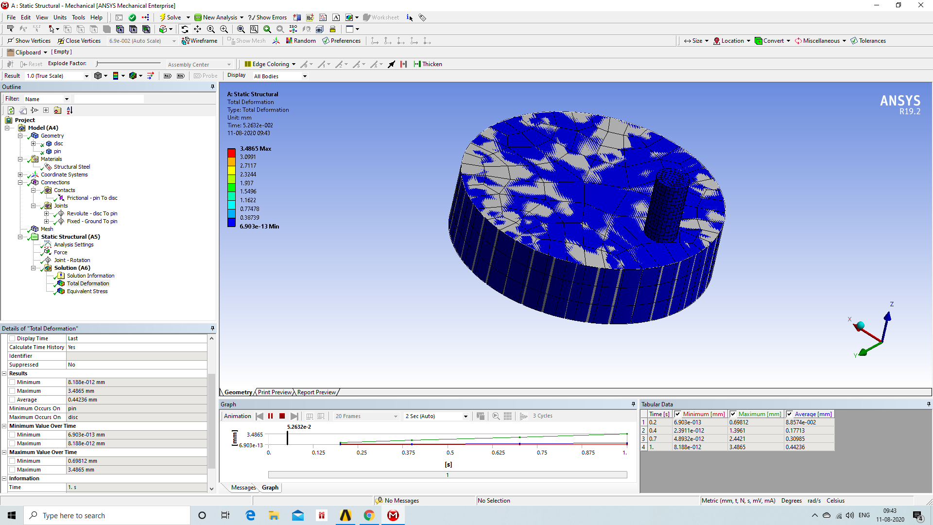
August 12, 2020 at 8:21 amAnsys EmployeeHello,nOk, thanks for clarifying. If you make the disc rigid, then the disk is idealized as a rigid body with 6 DOFs, so you will not see any elastic deformation. If you wish to model the above system in the drawing, then I just would like to ask why the disc is made rigid? Ansys Mechanical won't show stresses on a body that has behavior set to rigid.nThank you.nRegards,nSeannAugust 12, 2020 at 10:19 amSubscriberHello sir,nnThe disc and pin were by default rigid (model>geometry>stiffness behavior>rigid). I just made pin flexible, to get more deformation study on pin. but the deformation behavior were more on disc than pin in both the cases.nAlso, I want to picture what is happening at the contact point when the model is running. How to i make the disc transparent so that i can view from below? ndoes ansys provide the way to study the stress at contact area?.RegardsnAugust 12, 2020 at 10:41 pmAnsys EmployeeHello again!,nThanks for clarifying. Parts brought in from CAD default to flexible behavior. For the model you are simulating you would want both to be flexible. To see through the disc you can scope the results to just the pin, and the disc will show somewhat transparent. For example.nnHere is my assemblyn
n
August 12, 2020 at 8:21 amAnsys EmployeeHello,nOk, thanks for clarifying. If you make the disc rigid, then the disk is idealized as a rigid body with 6 DOFs, so you will not see any elastic deformation. If you wish to model the above system in the drawing, then I just would like to ask why the disc is made rigid? Ansys Mechanical won't show stresses on a body that has behavior set to rigid.nThank you.nRegards,nSeannAugust 12, 2020 at 10:19 amSubscriberHello sir,nnThe disc and pin were by default rigid (model>geometry>stiffness behavior>rigid). I just made pin flexible, to get more deformation study on pin. but the deformation behavior were more on disc than pin in both the cases.nAlso, I want to picture what is happening at the contact point when the model is running. How to i make the disc transparent so that i can view from below? ndoes ansys provide the way to study the stress at contact area?.RegardsnAugust 12, 2020 at 10:41 pmAnsys EmployeeHello again!,nThanks for clarifying. Parts brought in from CAD default to flexible behavior. For the model you are simulating you would want both to be flexible. To see through the disc you can scope the results to just the pin, and the disc will show somewhat transparent. For example.nnHere is my assemblyn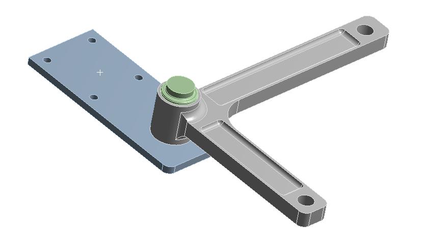 nHere i scoped to just a face (could be body, etc.) but I can see the stress through the other partnn
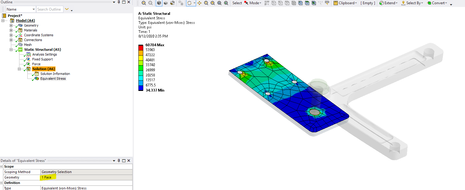 nTo look at the stress between the parts, you right mouse button on Solution and pick Contact Tool, then right mouse button that contact tool object and you can insert many results like status, pressure, gap, etc.nnKeep in mind to capture the behavior, depending on how high your force is, you will potentially need a fine meshnThank you.nSea
August 14, 2020 at 10:44 amSubscriberthank you sir for ur response.nit has really helped me.nComing to the contact part of solution, when i donot get the pictorial representation. only the graph results are shown. is there a way to get pictorial representation which diff color contour as we get for other results like stress etc?.nAugust 14, 2020 at 5:27 pmAnsys EmployeeHello,nYou are welcome. When you insert the contact took, and then right mouse button and insert pressure, you can use that to understand the normal contact pressure/stress. Likewise since you have frictional contact, you can insert frictional stress to see that result. Keep in mind the result is shown on the contact side of the pair, which your your case should be the pin. In the contact details you should set the behavior to asymmstric and confirm the contact side is the pin.nPlease watch this video on proper designation of contact/target If you wish to see the contact results on the disk, you change behavior to symmetric and you will get two pairs of contact. We also discuss that in this video. It may get confusing when you have two results on top of one another, so in the contact tool you can change the contact side from both to contact or target side to see results on just one side or the other. The results of the contact when you have two on top is generally the average of those results, but keep in mind a course mesh, you may see wide variation, so again, it may come down to what you are trying to capture, and your mesh resolution.n
nTo look at the stress between the parts, you right mouse button on Solution and pick Contact Tool, then right mouse button that contact tool object and you can insert many results like status, pressure, gap, etc.nnKeep in mind to capture the behavior, depending on how high your force is, you will potentially need a fine meshnThank you.nSea
August 14, 2020 at 10:44 amSubscriberthank you sir for ur response.nit has really helped me.nComing to the contact part of solution, when i donot get the pictorial representation. only the graph results are shown. is there a way to get pictorial representation which diff color contour as we get for other results like stress etc?.nAugust 14, 2020 at 5:27 pmAnsys EmployeeHello,nYou are welcome. When you insert the contact took, and then right mouse button and insert pressure, you can use that to understand the normal contact pressure/stress. Likewise since you have frictional contact, you can insert frictional stress to see that result. Keep in mind the result is shown on the contact side of the pair, which your your case should be the pin. In the contact details you should set the behavior to asymmstric and confirm the contact side is the pin.nPlease watch this video on proper designation of contact/target If you wish to see the contact results on the disk, you change behavior to symmetric and you will get two pairs of contact. We also discuss that in this video. It may get confusing when you have two results on top of one another, so in the contact tool you can change the contact side from both to contact or target side to see results on just one side or the other. The results of the contact when you have two on top is generally the average of those results, but keep in mind a course mesh, you may see wide variation, so again, it may come down to what you are trying to capture, and your mesh resolution.n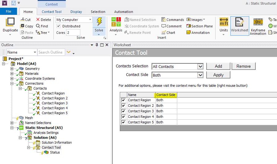 nnnRegards,nSeann
August 16, 2020 at 10:41 amSubscriberThank you so much for the detailed response.I will implement it and come to you again if i face any issuennthanks again nAugust 18, 2020 at 5:38 pmAnsys EmployeeHello,nYou are very welcome.nRegards,nSeannSeptember 4, 2020 at 11:22 amSubscriberHello sir,nnSo the simulation works when i give rotation in terms of degrees. However, i want to give the input in terms of Rotational velocity(rad/s).n Is there way i can do that?.the reason i am asking this because, i have run experiment with disc rotating at 300 rpm for 30 minutes. i want to replicate the same in ansysnnRegardsnSeptember 10, 2020 at 7:24 pmAnsys EmployeeHi there. My apologies on a delay. You can set this up as transient structural, and then specify the joint rotation to be in rotational velocity. Since you likely don't care about the dynamics you will want to turn off the time integration (as shown in the details). Also, don't for get to turn on large deflection. Please try this. Thank you.nnSeann
nnnRegards,nSeann
August 16, 2020 at 10:41 amSubscriberThank you so much for the detailed response.I will implement it and come to you again if i face any issuennthanks again nAugust 18, 2020 at 5:38 pmAnsys EmployeeHello,nYou are very welcome.nRegards,nSeannSeptember 4, 2020 at 11:22 amSubscriberHello sir,nnSo the simulation works when i give rotation in terms of degrees. However, i want to give the input in terms of Rotational velocity(rad/s).n Is there way i can do that?.the reason i am asking this because, i have run experiment with disc rotating at 300 rpm for 30 minutes. i want to replicate the same in ansysnnRegardsnSeptember 10, 2020 at 7:24 pmAnsys EmployeeHi there. My apologies on a delay. You can set this up as transient structural, and then specify the joint rotation to be in rotational velocity. Since you likely don't care about the dynamics you will want to turn off the time integration (as shown in the details). Also, don't for get to turn on large deflection. Please try this. Thank you.nnSeann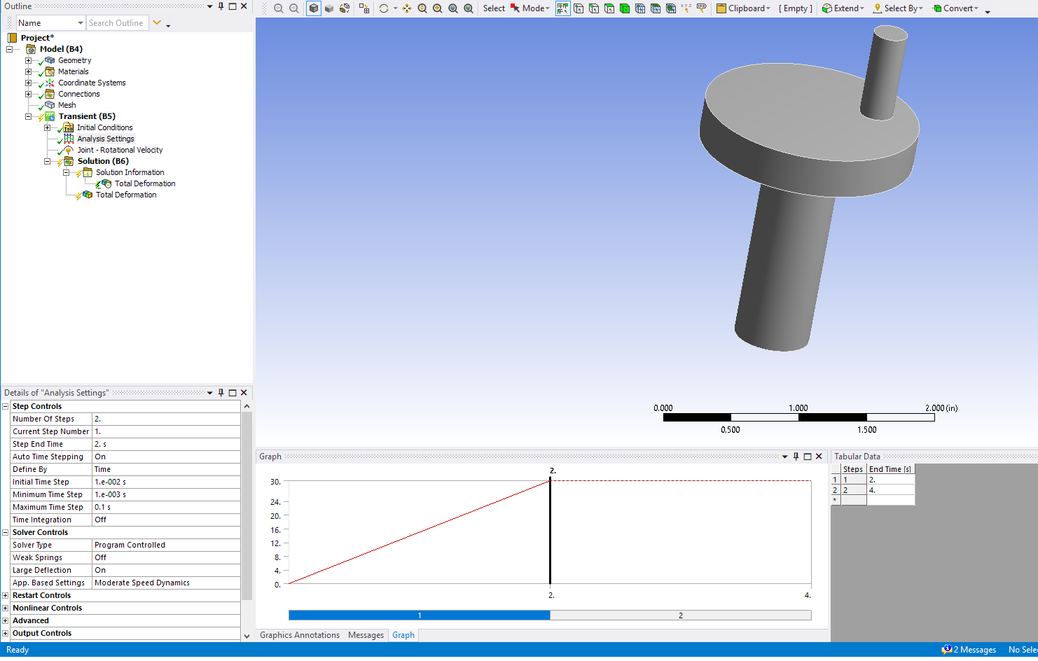 n
September 11, 2020 at 6:56 amSubscriberDear sirnnthank you so much.nnI am getting the following errors.n//nThe solver engine was unable to converge on a solution for the nonlinear problem as constrained. Please see the Troubleshooting section of the Help System for more information.n//nlastly, i want to calculate the wear in terms of height and volume. it will be great if you could guide me for the same.nnRegardsnSeptember 14, 2020 at 11:12 pmAnsys EmployeeHello,nSo, if you look in the Solution Information solver output, see what the error message states towards the end of the file, or type ctrl-f type error, and it will find errors in that file. If it is do to force not converging, you can then go to solution information and in the details set Newton Raphson Residuals to a number like 4. Try to run again, but this time when the job does not converge, it will have objects under that solution information branch that when you click on will highlight the region of the model with the force imbalance. It could be that the contact is the issue in which case you may need to change the contact parameters like the normal stiffness factor or penetration tolerance. It may also be that you are rotating too quickly and you need more substeps (or smaller time steps) in the analysis settings.nRegarding wear, this is a somewhat advanced topic. It is only support through commands nIn the help it is discussed in this location 4.19.1. Archard Wear Model nIn the help you can search for Contact Surface Wear Simulation and there is a MAPDL example, it is not setup for Workbench Mechanical, but that could be done. Keep in mind that when we do wear simulations, we actually don't need to have the disk spinning in the way we have discussed above, but rather it is done as explained in the help.nnOur AIC course on structural nonlinearities may help you with the core fundamentals of solving nonlinear problems so please also check out that free course. /courses/index.php/courses/structural-nonlinearity/nPlease see if his helps. Thank you.nnRegards,nSeaViewing 13 reply threads
n
September 11, 2020 at 6:56 amSubscriberDear sirnnthank you so much.nnI am getting the following errors.n//nThe solver engine was unable to converge on a solution for the nonlinear problem as constrained. Please see the Troubleshooting section of the Help System for more information.n//nlastly, i want to calculate the wear in terms of height and volume. it will be great if you could guide me for the same.nnRegardsnSeptember 14, 2020 at 11:12 pmAnsys EmployeeHello,nSo, if you look in the Solution Information solver output, see what the error message states towards the end of the file, or type ctrl-f type error, and it will find errors in that file. If it is do to force not converging, you can then go to solution information and in the details set Newton Raphson Residuals to a number like 4. Try to run again, but this time when the job does not converge, it will have objects under that solution information branch that when you click on will highlight the region of the model with the force imbalance. It could be that the contact is the issue in which case you may need to change the contact parameters like the normal stiffness factor or penetration tolerance. It may also be that you are rotating too quickly and you need more substeps (or smaller time steps) in the analysis settings.nRegarding wear, this is a somewhat advanced topic. It is only support through commands nIn the help it is discussed in this location 4.19.1. Archard Wear Model nIn the help you can search for Contact Surface Wear Simulation and there is a MAPDL example, it is not setup for Workbench Mechanical, but that could be done. Keep in mind that when we do wear simulations, we actually don't need to have the disk spinning in the way we have discussed above, but rather it is done as explained in the help.nnOur AIC course on structural nonlinearities may help you with the core fundamentals of solving nonlinear problems so please also check out that free course. /courses/index.php/courses/structural-nonlinearity/nPlease see if his helps. Thank you.nnRegards,nSeaViewing 13 reply threads- The topic ‘pin on disc’ is closed to new replies.
Ansys Innovation Space Trending discussions
- The legend values are not changing.
- LPBF Simulation of dissimilar materials in ANSYS mechanical (Thermal Transient)
- Convergence error in modal analysis
- APDL, memory, solid
- Meaning of the error
- How to model a bimodular material in Mechanical
- Simulate a fan on the end of shaft
- Real Life Example of a non-symmetric eigenvalue problem
- Nonlinear load cases combinations
- How can the results of Pressures and Motions for all elements be obtained?
Top Contributors
-
peteroznewman
 3977
3977 -
scabo
 1461
1461 -
Dennis Chen
 1272
1272 -
javat33489
 1124
1124 -
Shyam Prasad V Atri
1021
Top Rated Tags
© 2025 Copyright ANSYS, Inc. All rights reserved.
Ansys does not support the usage of unauthorized Ansys software. Please visit www.ansys.com to obtain an official distribution.
-


The Ansys Learning Forum is a public forum. You are prohibited from providing (i) information that is confidential to You, your employer, or any third party, (ii) Personal Data or individually identifiable health information, (iii) any information that is U.S. Government Classified, Controlled Unclassified Information, International Traffic in Arms Regulators (ITAR) or Export Administration Regulators (EAR) controlled or otherwise have been determined by the United States Government or by a foreign government to require protection against unauthorized disclosure for reasons of national security, or (iv) topics or information restricted by the People's Republic of China data protection and privacy laws.


