TAGGED: bandstructure, photonic-crystals
-
-
February 17, 2022 at 4:57 pm
schinta3
SubscriberHello,
In the rectangular bandstructure example (https://support.lumerical.com/hc/en-us/articles/360041566614-Rectangular-Photonic-Crystal-Bandstructure)
The k vectors are swept to values of 0.5 along the edges of the square brillouin zone. In general, since k vectors are represented by numbers, and ax,ay are equal to 0.5 microns
Let us say I have a similar rectangular lattice, with a lattice constant ax=ay=350nm.
Should the k vectors be swept to 350, represented as a number?
February 17, 2022 at 6:45 pmGuilin Sun
Ansys EmployeeFebruary 18, 2022 at 5:00 pmschinta3
SubscriberHello Thanks. I did notice this, however does this mean that the actual sweep ranges should extend all the way to 'a' with the correct units.
For example, if a=250nm, should the k values in the sweep be from 0 to 250
Or if a=0.250um should the k values in the sweep range from -0 to 0.25, sue to usage of SI units?
Best Sreyas
February 18, 2022 at 5:10 pmGuilin Sun
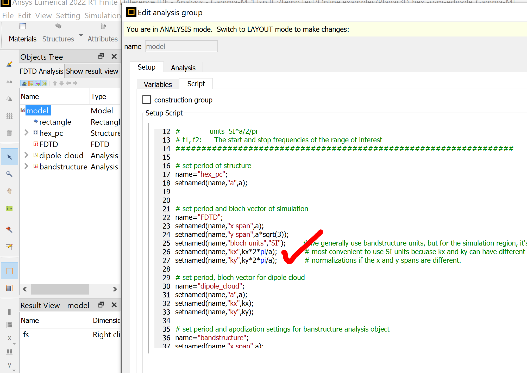
Ansys EmployeeIn SI unit yes the wave vector should be 2pi/a. but in the sweep, it samples it (0~0.5)*(2pi/a) and the result only uses (0~0.5). As mentioned previously, the absolute values of the wave vectors are applied. Maybe the file should not use "k", but use n_k to represent wave vector sampling n_k*k_max where k_max=2pi/a. The sweep kx, ky actually are the normalized values.
As you can see:

FDTD applies the correct wave vector whereas "dipole_cloud" is the normalized, sampling point. Do not be confused with the symbols.
February 23, 2022 at 6:52 pmschinta3
SubscriberHello One more question. In the above comment, the dipole_cloud object has kx and ky variables set, by whichever the sweep kx/ky pass. However, this screenshot is from the hex packed slab (https://support.lumerical.com/hc/en-us/articles/360041567454-Bandstructure-of-planar-photonic-crystal-with-a-hexagonal-lattice
However, the rectangular packed slab does not include this. Should it?
 https://support.lumerical.com/hc/en-us/articles/360042038213-Bandstructure-of-planar-photonic-crystal-with-a-square-lattice
February 23, 2022 at 7:59 pmGuilin Sun
Ansys EmployeeThey have different purpose.
The Bloch vectors are enforced in FDTD, in all the cases.
For hexagonal lattice, since its unit cell is not rectangular, but FDTD must be rectangle, so FDTD simulation has to simulate more than one unit cell. Therefor it needs phase compensation in the second unit cell, which needs the k values.
phase_offset = kx * dipole_offset_x * ((x>x(1))*2-1)/a*2*pi +
ky * dipole_offset_y * ((y>y(1))*2-1)/a*2*pi ;
phase_offset = phase_offset *180/pi;
AS you can see it has used the actual wave vector 2pi/a.
February 24, 2022 at 6:00 pmschinta3
SubscriberHello That makes sense regarding the phase compensation. One final question:
Again in the rectangular example, the bandstructure object is set with an offset z-axis:
 For a 200nm slab. I understand why the dipole cloud is all set to be randomly within the crystal slab, to excite all modes.
However, due to using relative coordinates, the time monitors may end up above the slab:
 As we are trying to calculate the in-plane band structure, shouldn't all time onitors be within the slab?
February 24, 2022 at 6:34 pmGuilin Sun
Ansys EmployeeTime monitors in the background or uniform material can give you the light line. But since we know it, you can modify the group span (x,y, or z spans depending on simulation settings) to limit the locations of the monitors inside the slab.
March 29, 2022 at 10:26 amSaraah
SubscriberThis was a great conversation: I am facing the same issue, so from what i get that:
If we have a square lattice where ax=ay= 600 nm, then we don't change the k value of k vectors (kx, ky) inside "model" variables, because there are calculated in teh script correctly, but we should change teh sweep values to match the period ? let's say if a= 600 nm, then the sweep should go to 0.6 ?
Is what I understood correct?
March 29, 2022 at 3:06 pmGuilin Sun
Ansys EmployeeHi, it depends on where the period ax ay are defined. If they are defined in "model" (and most of Lumerical examples are done so) when you do sweep using the built-in feature, you will choose the parameters which have unit there. it should be either 600nm or 0.6um:
 If you use your own separate script, it should be assigned as
period=linspace(0.5,0.6,11)*1e-6;
for (n=1:11){
setnamed("model","a",period(n));
run;
....
}
this is because in script everything is in SI, the International Units.
If you are not sure, just try to sweep 2 or 3 values, and then check the swept files and make sure the parameters are correctly set.
March 30, 2022 at 11:36 amSaraah
SubscriberThanks for teh explanation, I define my ax ay in the defined in "model". I understand setting the correct parameters and type part, but i am a little confused about what to start and stop? should I change the start and stop points, so that will include my period just like in your picture, from 0.5 to 0.7, so that 0.6 is in the middle?
April 4, 2022 at 12:11 pmGuilin Sun
Ansys EmployeeIn my screenshot, 0.5 to 0.7 has the unit of um, which is defined in "Type". You would do the same thing with proper type and value corresponding to the physical parameters, with unit. Just try 2 values and see if they can pass to the sweep file correctly.
Viewing 11 reply threads- The topic ‘Photonic Bandstructure Calculations’ is closed to new replies.
Innovation SpaceTrending discussionsTop Contributors-
4683
-
1565
-
1386
-
1242
-
1021
Top Rated Tags© 2025 Copyright ANSYS, Inc. All rights reserved.
Ansys does not support the usage of unauthorized Ansys software. Please visit www.ansys.com to obtain an official distribution.
-


