We have an exciting announcement about badges coming in May 2025. Until then, we will temporarily stop issuing new badges for course completions and certifications. However, all completions will be recorded and fulfilled after May 2025.
General Mechanical

General Mechanical

Topics related to Mechanical Enterprise, Motion, Additive Print and more.

performing Static and buckling analysis.

TAGGED: ,

    • amit.moond
      Subscriber

      Hi Guys,

      I want to determine collapsing force of a cylindrical shell having 1.5mm thickness due to clamp force generated by bolted torque. for that puprose initially i have performed static stuructral analysis and found that von mises stress comes out to be 1200Mpa on shell and clamp than i have done buckling analysis and strange results i got.

      1) as per yield strength of material my shell is failed becaouse 1200Mpa> 220MPa @ 18000N load.

      2) in buckling analysis i found critical load = 58000N

      can any one tell me how isit possible that in static it is failed but in buckling it is ok.


      Bolt pretension is 18000N.


      Static results:


    • dlooman
      Ansys Employee

      I guess you're saying the static "failed" because the stress is higher than yield, but apparently it didn't fail either.  Linear buckling would occur when the structure became unstable and that's unrelated to the yield stress.  For example, a very short column would never buckle even if the compressive stress was >> yield.

      • Prakash prakash
        Subscriber

        OK..

        I have one more query related to these results:

        • Actual field observation: as per customer feedback, no dent or deformation is oberserved on the surface even applying more than 18000N~ 16Nm torque.
        • FEM simulation:  As shown in above images, we are getting very high stresses which means material is failed at 18000N load.

        Could you tell what I need to do in order to validate simulation results with experimental??

    • amit.moond
      Subscriber

      Thanks Dave,

      I have another query related to same kind of geometry.

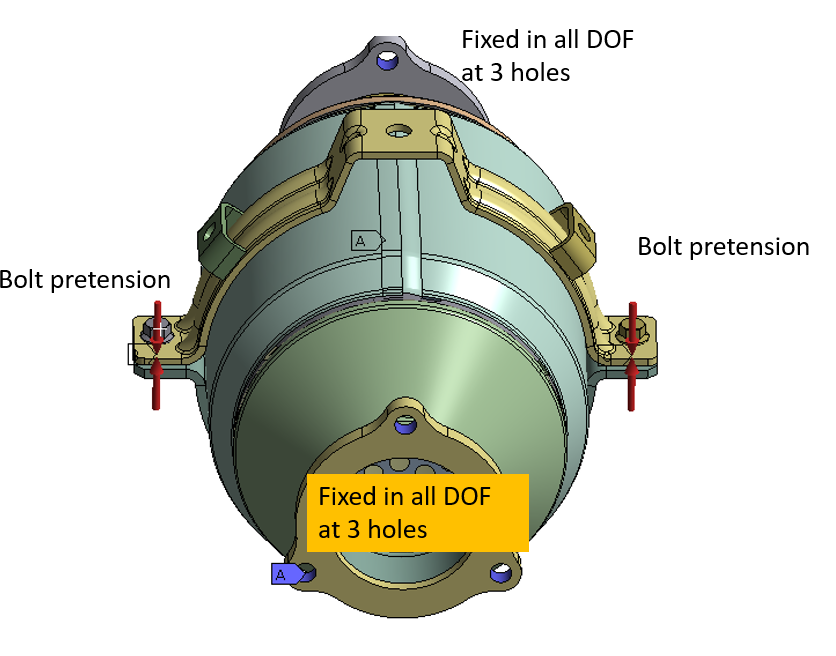
      I am applying the bolt pretension of 18000N but this much force is not able to tighten the clamps(attaching the image)

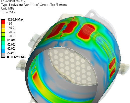
      Here the max stresses appear only on the bolt shank and around 6000MPa.

      i have tried with different type of connections.

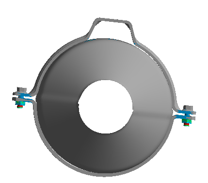
      Between clamp face and bolt head: bonded and Friction

      Here bonded connection behaves well as if i use friction contact then bolt and clamp moves apart.

      also the connection between the thiin metallic sheet and the clamp is no seperation. Here no seperation works well. Also i have to use dispacement constraints for X and Z as zero otherwise this will also not work.

      If i use frictional contact than again these two clamps moves apart from the thin metallic sheet.

      any comments?


    • dlooman
      Ansys Employee

      Probably better to create a new post for this contact issue.  It may be commented on by a contact expert.

    • Prakash prakash
      Subscriber

      OK..

      I have one more query related to these results:

      • Actual field observation: as per customer feedback, no dent or deformation is oberserved on the surface even applying more than 18000N~ 16Nm torque.
      • FEM simulation:  As shown in above images, we are getting very high stresses which means material is failed at 18000N load.

      Could you tell what I need to do in order to validate simulation results with experimental??

    • dlooman
      Ansys Employee

      Your highest contour range goes from 160 to 1221.  It's hard to tell how local the highest stress is.  Perhaps if the contact stiffness between the strap and the vessel was reduced the stresses would be better distributed.

      • Prakash prakash
        Subscriber

        OK,

        • How may I know the contact stiffness??
        • and how to reduce contact stiffness??
    • sachin.kumar
      Subscriber


      OK,

        • How may I know the contact stiffness??


      • and how to reduce contact stiffness??
      • should I go with  non-linear maerial properties(plastic region)??
    • dlooman
      Ansys Employee

      If using default contact stiffness you can check the output.  Or you can manually specify a lower factor than the default 1.0.  Perhaps 0.01.  Specifying nonlinear material properties makes the analysis more realistic.  

Viewing 7 reply threads
  • The topic ‘performing Static and buckling analysis.’ is closed to new replies.