TAGGED: continuity-residuals, fluent, monitor
-
-
February 26, 2023 at 7:10 am
Milne Ando
SubscriberG'day,
I noticed residuals were smoothed and turned to a straight line (as the pic shows); I don't know what happened. Can this affect the accuracy of data?
And I also wonder why residuals of continuity are always higher than residuals of x,y, and z velocity. Should I adjust any under-relaxation factor? (my case is 3D FSI simulation)
-
February 27, 2023 at 1:43 pm
Federico
Ansys EmployeeHello Milne,Â
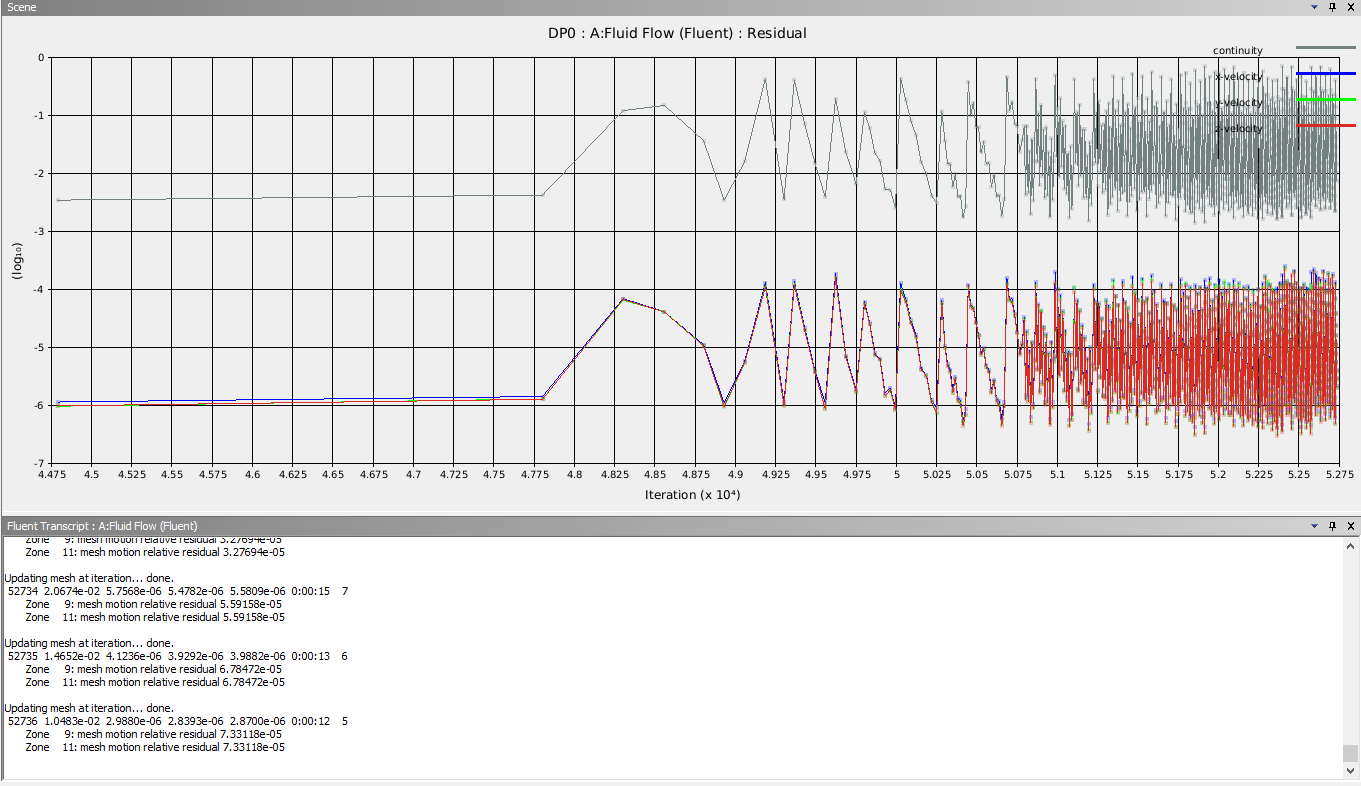
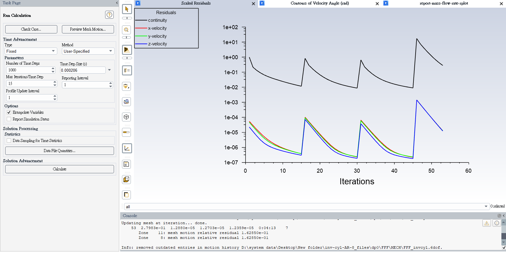
the pattern that you see with the residuals is related to how to choose to display them. In the Residuals Monitors dialog box, you can increase (or decrease) the number of iterations to plot or store. As your simulation progresses, Fluent may display less points from the earlier stages of the simulation to meet the number of Iterations to Plot, as defined. This does not in anyway impact your solution!
Regarding your second question, relative size of residuals is not as important as the trend of those residuals. If you see your continuity residuals decrease from iteration to iteration (for example, the behaviour of continuity follows the same patterns as your xyz velocities in your screenshot), this suggests that continuity equation is probably converging as well. You may check mass balance at the end of your simulation to double check that your results physically make sense.
I hope this helps.
-
February 27, 2023 at 2:55 pm
Milne Ando
SubscriberHello sir,
yes I've added report of mass flow rate to monitor the result. I'm still trying to find the optimal settings that are much stable and robust; however, the recommened values for factors seem not necessarily lead to good result. As the pic shows, residuals surged too quickly, even though my time step size was quite small. I used PISO scheme with PRESTO!, and under-relaxation factors of 0.5 for both pressure and momentum. The user guide says,
-
-
February 27, 2023 at 3:02 pm
Federico
Ansys EmployeeYou may want to increase the number of iterations per time step (at least initially), to see if this helps stabilize the solution.Â
Also I see that you have a dynamic mesh set up, make sure your time step is small enough to ensure that your moving boundary does not move more than 1 cell width per time step.
Â
Â
-
February 27, 2023 at 3:51 pm
Milne Ando
Subscriberhi,
yes, that time step size is the result from my calculation; time step size can't exceed 0.000206(s) in my case, for avoid crossing minimum cells. And in the beginning, Kármán vortexes had not formed yet, namely, the solid structure didn't oscillate initially. So it's strange and unreasonable that calculation diverged at early iteration.
-
-
- The topic ‘part of residuals smoothed and turned to a straight line, why?’ is closed to new replies.
- air flow in and out of computer case
- Varying Bond model parameters to mimic soil particle cohesion/stiction
- Eroded Mass due to Erosion of Soil Particles by Fluids
- Centrifugal Fan Analysis for Determination of Characteristic Curve
- Guidance needed for Conjugate Heat Transfer Analysis for a 3s3p Li-ion Battery
- I am doing a corona simulation. But particles are not spreading.
- Issue to compile a UDF in ANSYS Fluent
- JACOBI Convergence Issue in ANSYS AQWA
- affinity not set
- Resuming SAG Mill Simulation with New Particle Batch in Rocky
-
3862
-
1414
-
1220
-
1118
-
1015
© 2025 Copyright ANSYS, Inc. All rights reserved.