TAGGED: metasurface, plasmonics
-
-
October 25, 2024 at 9:44 am
javi_pi
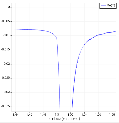
SubscriberHello! I'm trying to model a metallic grating coupler to dynamically show the plasmonic effect to my students. It is basically 2D simulation of a unit cell with periodic boundary conditions along the x axis and PML along the y axis. However, some kind of oscillation appears whenever I calculate the reflexion profile. I've checked the knowledge base and followed the advices. Then, I tried the calculation with the energy monitor behind and in front of the source, increasing the FDTD region's height, reducing the autoshutodd value to 10^-6 and changing the mesh settings. Unfortunately, the oscillations are still there. Does anyone have any idea on how it is happening? It is not an important matter but it's something I'm curious about because it is a quite straightforward model apparently. I attach some images to illustrate the problem.
-
October 25, 2024 at 11:01 pm
Kirill
Forum ModeratorHello Javi,
Thanks for reaching out!
1. It seems that your simulation structure may have high diffraction angles. I suggest setting the PML profile to 'Steep angle' and perhaps increasing the number of layers even further.
2. Consider adding a movie monitor, as it can sometimes help to better understand the physical effects.
3. Set the field monitor inside the metal, crossing through the PML boundary, to verify that the reflection from the PML boundary is sufficiently low. Don't forget to enable the 'Record data in PML' option in the advanced settings of the monitor.
4. Be mindful of the resonances in your structure. They may lie outside the spectral region of interest (1.44–1.59 µm) but can still be excited by your source. You may want to adjust the spectral range of the source to avoid unwanted resonances in your system.
5. The resonance decay time can be substantially long. Increase the simulation time to ensure that there is no residual energy left in the system.
It’s difficult to predict which factor plays a bigger role in your simulation but try testing them individually to evaluate their effects. Also check if you could get some insights from the following resources: Convergence testing process for FDTD simulations, Selecting the best mesh refinement option in the FDTD simulation object, and Plasmonics - list of examples.
Best regards,
Kirill
-
- You must be logged in to reply to this topic.


-
4597
-
1495
-
1386
-
1209
-
1021

© 2025 Copyright ANSYS, Inc. All rights reserved.


