-
-
March 18, 2020 at 10:55 am
sk8thoma
Subscriberhello everyone,
For my MSc research project I am comparing different designs with ansys. I am not really good to understand static structural warning messages and how to solve them. I have linked my simulation file to this message.
here is a picture of my boundary conditions, I am not sure about what information you need to help me so do not hesitate to ask me all you need. As you can see I have conflicts with MPC contact regions or remote boundary conditions and apparently not enought constaints to prevent rigid body motion
thanks in advance
-
March 18, 2020 at 3:15 pm
Wenlong
Ansys EmployeeHi,
Sometime when the model gets complex with joints and ends up with rigid body motion, it may be a good idea to conduct a Modal analysis to check what rigid body motion you have. This can help you quickly identify the cause of the problem.
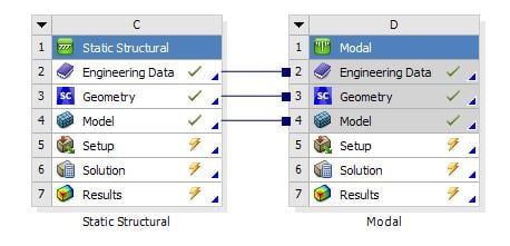
A related Modal analysis can be easily done by dragging a Modal Analysis system to the "model" of the Static Analysis so that you don't need to define these joints again.
Regards,
Wenlong
-
March 18, 2020 at 4:10 pm
sk8thoma
SubscriberHi Wenlong,
thanks for your help
1) I am not sure to understand the meaning of rigid body motion as all the components in my analysis are deformable
2) I was not sure about how to run an analysis with rigid bodies, instead I have created a material called "rigid" with a young's modulus of 2E+20Pa
3) I have run the modal analysis but I am not sure about what to conclude of it
here is another screenshot with the boudaries conditions.
In A it is a remote displacement, everything is fixed but the rotation arround the x axis (which is free).
In B it is a remote displacement, everything is fixed but the rotation arroud the x axis and the translation along the z axis (which are free).
this way, the front fork is able to move and rotate as it would be on a bicycle in the real world.
the brown component (the frame) is flexible and the gree/blue ones are flexible with a high Young's modulus.
-
March 18, 2020 at 6:16 pm
Wenlong
Ansys EmployeeHello,
Rigid body motion means a body translates or rotates without producing any strain. It can happen to both flexible and rigid body. If you have a rigid body motion in simulation, it means some DOF is not properly constrained. For example, in your bike model, the front fork can rotate in the local z-axis, and if you don't apply remote displacement to control the Rz DOF, it will show you a message "Rigid body motion" or "Small pivoting term in the matrix".
Back to your question, about the warning about "remote boundary conditions may conflict with another", here is an explanation: https://ansyshelp.ansys.com/account/secured?returnurl=/Views/Secured/corp/v201/en/wb_sim/ds_one_or_more_mpc.html?q=remote%20boundary%20conditions%20may%20have%20conflicted%20with%20another. It can mean more than one MPC or remote BC is defined on the same face or body.
If you have trouble viewing the above link, please refer to this post: /forum/forums/topic/how-to-access-the-ansys-online-help/
This is off-topic, but for your simulation, you may also use "joint" to simplify the simulation process: https://ansyshelp.ansys.com/account/secured?returnurl=/Views/Secured/corp/v195/wb_sim/ds_Joints_types.html?q=joint%20types
Further questions? Please let me know.
Regards,
Wenlong
-
March 19, 2020 at 3:37 pm
sk8thoma
Subscriberthank you for your explanations Wenlong,
I have check all the BC one by one and I have find something.
- if I apply more than one force/remote force on the same surface, I have the waring "Two or more remote boundary conditions are sharing a common face, edge, or vertex. This behavior can cause solver overconstraint and is not recommended, please check results carefully. You may select the offending object and/or geometry via RMB on this warning in the Messages window."
and "One or more MPC contact regions or remote boundary conditions may have conflicts with other applied boundary conditions or other contact or symmetry regions. This may reduce solution accuracy. Tip: You may graphically display FE Connections from the Solution Information Object for non-cyclic analysis. Refer to Troubleshooting in the Help System for more details."
if I only apply one force on the surface, then the warging message dissapear
-when I allow the displacement + the rotation on the remote displacement B (cf. my previous post) I have the warning message "Not enough constraints appear to be applied to prevent rigid body motion. This may lead to solution warnings or errors. Check results carefully." if I only allowed the rotation, the message dissapear.
here are my questions,
Is it a bad idea not put more than one force on a surface or can I ignore the two warning message I get ?
because I want bike for to rotate arround the z axis and tanslate allong the x axis, should I perfrom another analysis than Static structural or not ? (I mean, can I trust the result I get ?)
sorry I am not an expert with ansys as I had only performed simple analysis before.
-
March 19, 2020 at 7:00 pm
Wenlong
Ansys EmployeeHi,
1. Applying several forces on a surface shouldn't be a problem. The warning happens when you are putting two displacement controls on the same surface. It may or may not cause an overconstraint issue. But warning message does necessarily mean your model set up is wrong. It is just trying to bring to your attention possible problems with the setup. For example:
Case (a), you have a displacement control that moves a shaft in the axial direction while having a remote displacement to make it rotate about the axial axis, then it won't cause conflict because rotating it doesn't contribute to any changes in the x coordinate, and you can ignore the message in this case.
Case (b), you have a displacement control trying to move the shaft in the y-direction, and the same remote displacement control is rotating it in the axial direction, this time there will be a conflict between these two BCs, as rotating in the axial direction does change the y-coordinate of a point on the shaft. And you should consider changing your BCs.
2. What result are you trying to obtain from the simulation? A static structural analysis won't solve if you have a rigid-body motion, but after hearing your simulation objective, there should be a way to get around this.
Regards,
Wenlong
Useful Links
-
March 20, 2020 at 9:13 am
sk8thoma
SubscriberHi,
Ok I think I start to understand
The purpose of my studdie is to analyse the stress on the bicycle frame only (I am not interested by the fork nor the seat post). The other parts are present to apply fixture or loads. In my studdy, the frame is in aluminium and the other parts are made of a custom material that I have called "rigid material" with a Young's modulus of 2E20 Pa.
In the real word, a bicyle is sat on two wheels, I have represented the wheels by a remote displacement. Because I am not interested by the fork, is it really an issue to have my warning errors ?
Should I represent the wheels to get better results ?
thanks in advance
-
March 20, 2020 at 2:18 pm
Wenlong
Ansys EmployeeHi thomasrtg,
Thanks for clarifying the model set up. In my opinion, you don't need to include other parts (fork, seat, and wheel) into the simulation. Moreover, assigning then an extremely large Young's modulus may lead to inaccurate results. Here is what I would apply as the BCs as a suggestion.
Regards,
Wenlong
If you find the post answers your question, please check the "Is Solution" button to help others, otherwise, feel free to follow up.
-
March 20, 2020 at 4:34 pm
sk8thoma
SubscriberHi,
I had already done your suggestion at first however I was not sure to trust the results.
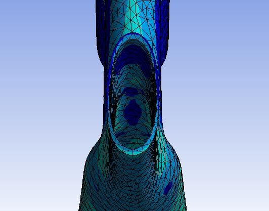
As you can see these area are deformed, however in the real world, bearings are present and I was thinking that the stress would be applied to the bearings more than to the frame ( I hope you understand what I mean).
what is your opinion about my suggestion and what would be your recommandation ?
regards,
Thomas
-
March 25, 2020 at 4:59 pm
Wenlong
Ansys EmployeeHi Thomas,
Apologies for my late reply. Somehow I don't get a notification of your post.
To make the frame end-section deform uniformly, you can try changing the behavior of the remote displacement to "Rigid" (Reference: https://ansyshelp.ansys.com/account/secured?returnurl=/Views/Secured/corp/v201/en/wb_sim/ds_Remote_Displacement.html?q=remote%20displacement%20behavior)
If you are concerned about the deformation scale displayed, you can go to the "result" tab, and change the display scale.
Regards,
Wenlong
Useful Links
-
April 12, 2020 at 9:54 am
sk8thoma
SubscriberHi, Sorry for the delay, I haven't seen your answer.
as there is bearings I still want to perfom this study with several solids.
I think I have found the solution to my problem, I will show you my procedure, if you think it is correct then I'll mark this topic "solved"
step 1
open the geometry in space claim and slice each solids so there is no more than one BC per face.
Step 2
in static tructural, connect the sliced body together using "contact -->bonded"
Step 3
Apply the BC conditions (supports and forces)
Step 4
perform the simulation
Step 5
enjoy your results without anys warning messages.
I hope my explanations are clear and moreover I hope my solution is correct

-
- The topic ‘one or more mpc contact regions or remote boundary conditions may have conflicts…’ is closed to new replies.


-
4633
-
1535
-
1386
-
1225
-
1021

© 2025 Copyright ANSYS, Inc. All rights reserved.


