TAGGED: nonlinear, normalization
-
-
December 4, 2023 at 6:04 pm
Chieh Tsao
SubscriberHi all,
I have been doing nonlinear simulations recently and have a question about normalization.
Based on the Lumerical website, I need to use nonorm and write the script for normalization. However, in this case, the unit is Watts per Hertz squared. How could I convert it into Watts? I saw someone just multiply the value by (c/lambda)^2, but the values I got from this method don't make sense. I am wondering what the correct way to convert the unit is.
Thanks!
-
December 4, 2023 at 8:18 pm
Dimitris Polyzos
Ansys EmployeeHello ,
I would suggest to use the following script, where P_watt will return your power in watts. You can use the Poyinting-vector and then integrate it in space, and it gives the same result. PLease refer to this link for more infomration: https://optics.ansys.com/hc/en-us/articles/360034397034-Units-and-normalization-conventions-in-Lumerical-solvers
T=transmission("monitor"); # this function always gives normalized result.
f=getdata("monitor","f");
p_watt_Hz=T*sourcepower(f); #power spectrum
P_watt=integrate(p_watt_Hz,1,f); # in WattI hope I helped. Please let me know how it went and feel free to contact for further assistance.
Kind regards
Dimitris
-
December 4, 2023 at 9:09 pm
Chieh Tsao
SubscriberHi Dimitris,
Thanks for the reply!
I think I should attach my script. This is the script I used (Nonlinear and gain methodology – Ansys Optics)
# disable CW norm
nonorm;
# get poynting vector from monitor.
Poynting = getresult("monitor","P");
# integrate real Pz to get power.  Assume this monitor is 2D, in the XY plane
# This quantity will have units of Watts/Hz^2 due to the use of the nonorm state
Trans = 0.5 * integrate(real(Poynting.Pz),1:2,Poynting.x,Poynting.y);
# package data into dataset
T = matrixdataset("T"); # initialize dataset
T.addparameter("lambda",c/Poynting.f,"f",Poynting.f); # add frequency parameter
T.addattribute("T",Trans);  # add transmission attribute
# optionally, visualize data
visualize(T);
Since I am doing nonlinear simulation, it seems that cwnorm doesn't make sense in this case.In your script, do you get cwnorm data?
-
December 5, 2023 at 8:47 am
Dimitris Polyzos
Ansys EmployeeHello Chieh,
Field monitor gives CW results that are normalized to source spectrum in CWnorm state. The returned data from Transmission in my script code are normalized, indeed.
I would suggest to have a look at this link: https://optics.ansys.com/hc/en-us/articles/360034394234-Understanding-frequency-domain-CW-normalization
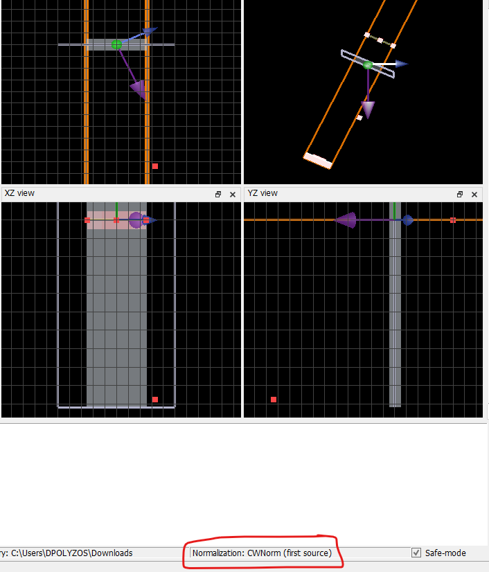
Normally, the simulation will return the cwnorm data. You can see in the picture below that normalization
I hope I helped. Please feel fre to conact me for further assistance.
Kind regards
Dimitris
-
December 12, 2023 at 1:35 pm
Riccardo Brameri
SubscriberHi all,
I’m also doing simulations in nonlinear optics and I’m experiencing the same problems.
Since I need to evaluate the efficiency (defined as P_shg/P_source^2 or P_dfg/P_pump/P_signal), I need to know the Power at the different frequencies and can’t just use it in W/Hz2.
I have read the replies, but the integration over frequency just gives the total power, which is way lower than the normalized power. While the example script just retrieves the non-normalized power, it’s the definition of the command getdata(“monitor”,”power”)
I tried using a time monitor to obtain the power, of which I then did the Fourier transform and this seems to work. Here is the code:
f=getdata("monitor","f"); #get frequency span from a frequency monitor
P=pinch(getdata("temporal_monitor","power")); #get the power from the temporal monitor
t = getdata("temporal_monitor","t");
Pw = abs(czt(P,t,2*pi*f));
Let me know if this works also for you
Kind regards
Riccardo
-
December 12, 2023 at 3:32 pm
Dimitris Polyzos
Ansys EmployeeHello Riccardo, I think there is a mistake in your code or I misunderstood something. The temporal monitor is a timemonitor? If yes, there is no power parameter in temporal_monitor making the script not working when I try to use it in a model.
It would be helpful if you could share some screenshots of your model, or script to create it at my PC in order to be aligned with the results we obtain.
Please refer to this article: https://optics.ansys.com/hc/en-us/articles/4412965651475-How-to-calculate-the-source-power-
Kind regards
Dimitris
-
December 12, 2023 at 4:03 pm
Riccardo Brameri
SubscriberHello Dimitris,
yes I'm using a timemonitor
In "Data to record" it is possible to select also Poynting vector and power, without having to calculate those after
Now I’m just simulating a silica waveguide created quite randomly just to be able to do fast simulations and solve this problem
Can't see the article, seems a part of the link is missing -
December 13, 2023 at 10:49 am
Dimitris Polyzos
Ansys EmployeeHello Riccardo,
Thanks for your reply. You are correct, I was trying to enable the power in a time monitor, but eventually there was an issue with my model and I couldn't. However, I can enable it know and get the power data.
Thanks for the clarification that your model is randomly created. I checked your script and it seems to work on my model as well. What you are really do is to calculate the nonorm power, frequency dependent, directly from time monitor. This link explains the nonorm (what you apply) and the cwnorm difference.
You can see the article here: How-to-calculate-the-source-power-
I also add some useful links:
1. Understanding-frequency-domain-CW-normalization
2. Units-and-normalization-conventions-in-Lumerical-solvers
I hope I helped. Please let me know if you need further assistance.
Kind regards
Dimitris
-
- The topic ‘normalization in nonlinear optics’ is closed to new replies.


-
4618
-
1530
-
1386
-
1209
-
1021

© 2025 Copyright ANSYS, Inc. All rights reserved.


