General Mechanical

General Mechanical

Topics related to Mechanical Enterprise, Motion, Additive Print and more.

Nonlinear Impact Analysis with preloaded bolts using Transient Structural

    • Shady Alissa
      Subscriber

      Hello I am trying to run a rectangular plate that is bolted on to an I-beam. This plate will receive an impact of 5 m/s from an external dropped object. Now I have not been able to get the solution to converge whenever I preload the bolts in transient. I created a static structural system where I was able to successfully preload the bolts. My question is there a way to take the pre-stressed model I have in static structural and use it in transient structural? This is for a non-linear analysis. Or is there a way where I can apply pre-load tension to the bolts and apply a 5 m/s impact on to the plate all in transient structural? Because so far I have not been able to achieve convergence in transient structural with pre-loaded bolts. As you can see in the picture I am using beam connections as the bolts and the beams the plate is attached to are surface models. The plate itself is a 3D body. I have also attached a picture of my analysis settings for transient and the bolt pretension settings I currently have applied. Any help would greatly be appreciated. 

    • peteroznewman
      Subscriber

      Is that Velocity you show in the image a Boundary Condition or an Initial Condition?

      You want an Initial Condition because then the structure absorbs the impact of the object and converts the kinetic energy into strain energy and plastic work on the plate and I-beams. As the energy conversion takes place, the velocity will reduce down to zero and possibly reverse direction during a rebound phase.

      By contrast, a Velocity Boundary Condition imposes a constant velocity for all time.  You don't want that.

      Step 1 is when you apply the preload in Bolt Pretension. During Step 1, turn off Time Integration in the Analysis settings. That will make step 1 behave like a static structural model. Keep Time Integration Off during Step 2 when the Bolt Pretension is set to Lock.  Step 3 is when Time Integration is On and the Transient Dynamics happens. I haven't tested this prior to writing my reply, but I seem to recall there is an issue where Initial Conditions only work in Step 1. See what you find out when you try this and let me know in your reply. If there is an issue, there should be a workaround where the bolt preload can be done in a prior analysis so that Transient Dynamics can be done in Step 1 with the correct Initial Conditions for the Velocity of the object.

    • Shady Alissa
      Subscriber

      The model is now converging however its not ouputting the results I want. The impact object is displaced into space for some reason after running the analysis. I am using an initial condition velocity in my setup, However I am getting a number of warnings for my beam connections. I am also getting a contact warning even though the contact tool shows everything is normal? I have setup my analysis settings per the 3 steps but not sure why the impact is flying off into space. 


    • Shady Alissa
      Subscriber

      I have defined my preloads at the bolts and my analysis settings for the 3 time steps. 


    • peteroznewman
      Subscriber

      You show results .03 s after impact. Calculate how far an object moving at 196.85 in/s travels in .03 s, it is 5.9 inches.  How high above the plate is the object in your image?  You need to look at results over a much shorter time interval.

      How thick is the plate?  Assume a .25″ thick plate. To observe the object travelling that distance, the time step would need to be .0013 s.  Try .0001 s for the Initial Time Step, .001 for the Maximum Time Step and .00001 s for the Minimum Time Step.

      However, I see that for Step 3, you are already using .001 s for the Initial Time Step. Maybe the Initial velocity is being applied from time=0.  Try suppressing the bolt pretension load and changing the simulation to a 1 step solution with the time steps I mentioned above.  You should see many time steps as the object deforms the plate and begins to rebound. The end time can be about 0.01 s.  If you get a good result, then go back to 3 time steps but now make the end time of step 1 be 1e-6 s, the end time for step 2 to be 2e-6 s and the end time for step 3 can be 0.01 s and see if that looks similar to the one step results.

    • Shady Alissa
      Subscriber

      The plates thickness is about 0.4 inches and the object is sitting right on top of the object. The object itself is about 4 inches in height. I reduced the time steps per your suggestions but I am still experiencing the same issue. When I use 1 time step the object deflects normally on the plate with no issues. However when i set it to 3 time steps and include the preload I still have the issue where the object ends up at an arbitrary point in space. Not sure whats happening with the impact?

    • peteroznewman
      Subscriber

      I found this discussion, where Dave Looman from ANSYS describes a new capability in ANSYS 2022R2 to apply Initial Conditions (IC) in a particular load step (LSIC). 

      IC, NODE, Lab, VALUE, VALUE2,NEND, NINC, LSIC

      In 2021R2, that is not possible.

      IC, NODE, Lab, VALUE, VALUE2,NEND, NINC

      This means the 3 step solution I mentioned above cannot work in 2021R2. Can you upgrade to a newer version of ANSYS?

    • Shady Alissa
      Subscriber


      I have downloaded 2023 R2. However I do not see the option to add Load step initial condition for the velocity? Or should I just run the solution you mentioned previously in in 2023 R2? With the time steps mentioned


    • peteroznewman
      Subscriber

      ANSYS has a Solver that reads an input text file written in the MAPDL language. In the ANSYS 2022R2 and later versions, the MAPDL command IC got the new capability I mentioned in my reply.

      ANSYS Workbench/Mechanical is a preprocessor that provides menus and dialog boxes to graphically create the MAPDL input text file that gets sent to the solver. Workbench/Mechanical does not support every capability that the MAPDL language has, just the most useful ones.  It may take a few years for a new capability of the MAPDL language to be supported in the menus and dialog boxes. Some commands will never be added to Workbench/Mechanical.

      In Mechanical, you can click on the Transient Structural branch of the outline and click the Write Input File button.  The text file is written in the MAPDL language and uses a .dat file extension.  Open this input file using a text editor, search for the IC command, add a , 3 to then end of the command and save the file.

      Use the Windows Start menu to start the Mechanical APDL Product Launcher, on the Job Name line, Browse to the input file you edited and click the Run button to start the solver.  When the solver has finished running, read the results into Workbench. How do you do that you ask?  I don’t recall but there may be a discussion in the forum on how to do that.

      Workbench/Mechanical supports Command objects that allow you to insert commands into the input text file. This is how you get an unsupported MAPDL command into an input file created by Workbench/Mechanical.  To do it this way, copy the one line for the IC command out of your input file and paste that into a Command object in Mechanical.  I am not sure if some other command is needed on the line above the IC command, possibly not.  There are two places to insert the Command object: Under the Transient Structural branch of the outline or the Solution branch of the outline. I think the IC command belongs in the Solution branch. By using a Command object, you just click the Solve button in Mechanical and the results are automatically read in when finished.  This is nicer than the more manual way described above, but may be more difficult to get right the first time.

    • Shady Alissa
      Subscriber


      I think I found the IC command you mentioned but now I am wondering do I apply the ,3 to all the velocity components (x,y,z) or just the y component where I have it set to 196.86 in/s and the rest are 0? Also I want to confirm if this is the IC command you suggested to add the ,3 to at the end. I went ahead and input ,3 at the end for each component though now when I try to run it in the mechanical APDL solver it provides this error message? 


    • peteroznewman
      Subscriber

      Look at the format for the IC command I provided above or look in the ANSYS Help system yourself. You need a total of seven commas and the 3 comes after the seventh comma.

      The Lab parameter should have VELX, VELY and VELZ for velocity initial conditons. The text you show is wrong because it has UX, UY and UZ which are for displacement initial conditions.

    • Shady Alissa
      Subscriber


      I searched the dat file to locate the commands you mentioned but this dat file only displays the displacement commands? It even shows the UY as 196.85 which is the value I set for the initial velocity going in the y direction. As you can see for defining the initial velocity there is only UX, UY, YZ. There is no VELX, VELY, VELZ? Also I wanted to ask if I go the command block approach in mechanical do I need to suppress the initital conditions velocity and add my editied line of code under the transient branch?


    • peteroznewman
      Subscriber

      I reread the paragraph from ANSYS Help that I copied above. Mechanical wrote ic,all,ux, which is not wrong, the Lab parameter ALL means use all appropriate labels, so it is applying an initial velocity, the second parameter is a value that describes the direction. Note that there are two commas in a row then the value you entered.  The important point is that you must have seven commas before you type the 3.

      ic,all,uy,,196.85,,,3
    • Shady Alissa
      Subscriber


      Ok so I tried using the APDL product launcher approach where I edited the dat file and added the ,,,3. I looked up how to read the dat file into mechanical and essentially you need to convert the dat file into a cdb file in the APDL product launcher and insert an external model where it can read the cdb file into mechanical. However when I try to do this I get a meshing error as shown here. I did notice when I open the cdb file to crosscheck the code with the dat file, half of the code is erased in the cdb file and I am not sure why? I have also tried to do it via the command block method in mechanical where I posted these 3 lines of code under the transient branch but it runs the analysis as if I didn't insert a command block. 

      ic,all,UX,,0.,,,3
      ic,all,UY,,196.85,,,3
      ic,all,UZ,,0.,,,3


    • peteroznewman
      Subscriber

      Ok, you are getting closer. You have a Workbench project that has the mesh, all the connections, loads and boundary conditions. The project file has a name such as Impact.wbpj and there is a folder called Impact_files that has lots of files.

      In Mechanical, you wrote out a .dat Ansys input file.

      In a Text Editor, you edited the .dat file to put in the ,,,3 that Mechanical won't do for you on the IC commands.  You don't use the ANSYS Product Launcher to edit the .dat file, you use a Text Editor such as Notepad++.

      You use the ANSYS Product Launcher to submit the edited .dat file (Job Name) to Run the Solver.  The solver will generate some files in the directory you told it to use.  One of those files is a text file called Solve.out.  You can open Solve.out with a Text Editor and read the lines to see if it ran the solution without an error.  Another file created by the solver is the *.rst file.  This is the result file that has all the displacements, velocities, stresses and strains for every node and element in the model.  This is the file you can read into Mechanical to plot the results.  Open your original Workench project, Impact.wbpj, open Mechanical and read in the .rst file.

    • Shady Alissa
      Subscriber

      Ah ok. Can you explain how I can go about doing via inserting the command object in mechanical? I inserted the command object in the transient structural branch where I added the IC command along with the nodes attached to it and when I hit solve it doesnt solve it with the inputs i added. I noticed there are ARG# down in the bottom left of the details bar for the command object. However I am not sure what to input or code into this command object to get it to run the analysis with the configured initial velocity. I am trying to figure this out in order to redefine the standards of how to perform this type of analysis at my job but am currently stuck with what to input exactly for the command snippet to work. Currently this is what I inputted but does not seem to work.

    • peteroznewman
      Subscriber

      Were you successful following the manual workflow I outlined in my previous reply?  You want to know the manual method worked before you try to do it with a Command Object.

      When you try the Command Object, it is just the three IC lines. In your screen snapshot, you seem to have included a lot of the .dat file. That is wrong.

    • Shady Alissa
      Subscriber

      I tried doing it both ways however the end result is still the same. The object does not move at all. 

    • peteroznewman
      Subscriber

      Unfortunately, I am not an expert at writing APDL code.  Hopefully an expert will reply. In the mean time…

      Open ANSYS Help and paste the following address into the browser: 

      https://ansyshelp.ansys.com/account/secured?returnurl=/Views/Secured/corp/v241/en/ans_cmd/Hlp_C_IC.html

      Read the command syntax. 

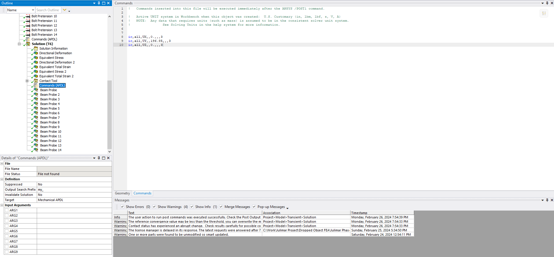
      IC, NODE, Lab, VALUE, VALUE2, NEND, NINC, LSIC

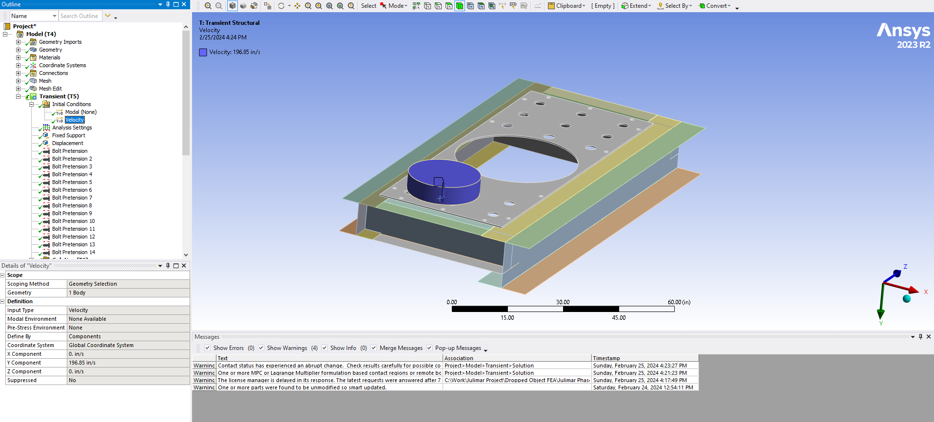
      NODE can be ALL if the nodes were previously selected. A component name can be substituted for NODE. I believe that when you create a Named Selection, that name is a component name for the solver. Create a Named selection for the nodes in the object. Use the name N_Obj for example.
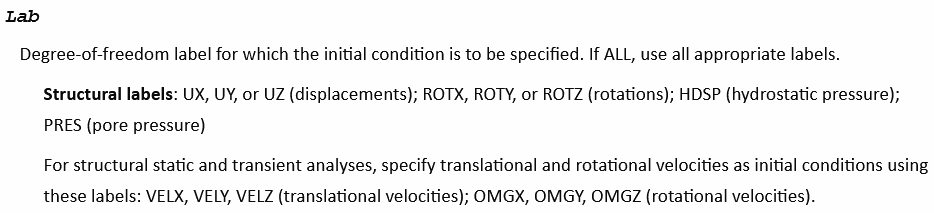
      Lab should be VELY. 

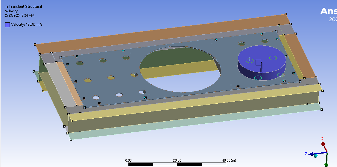
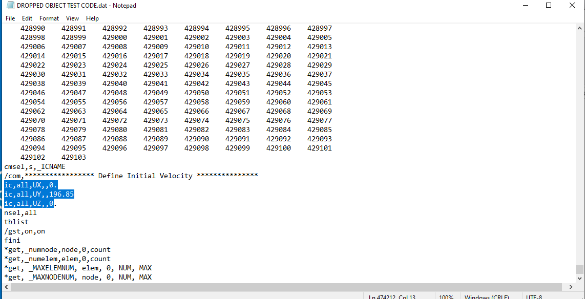
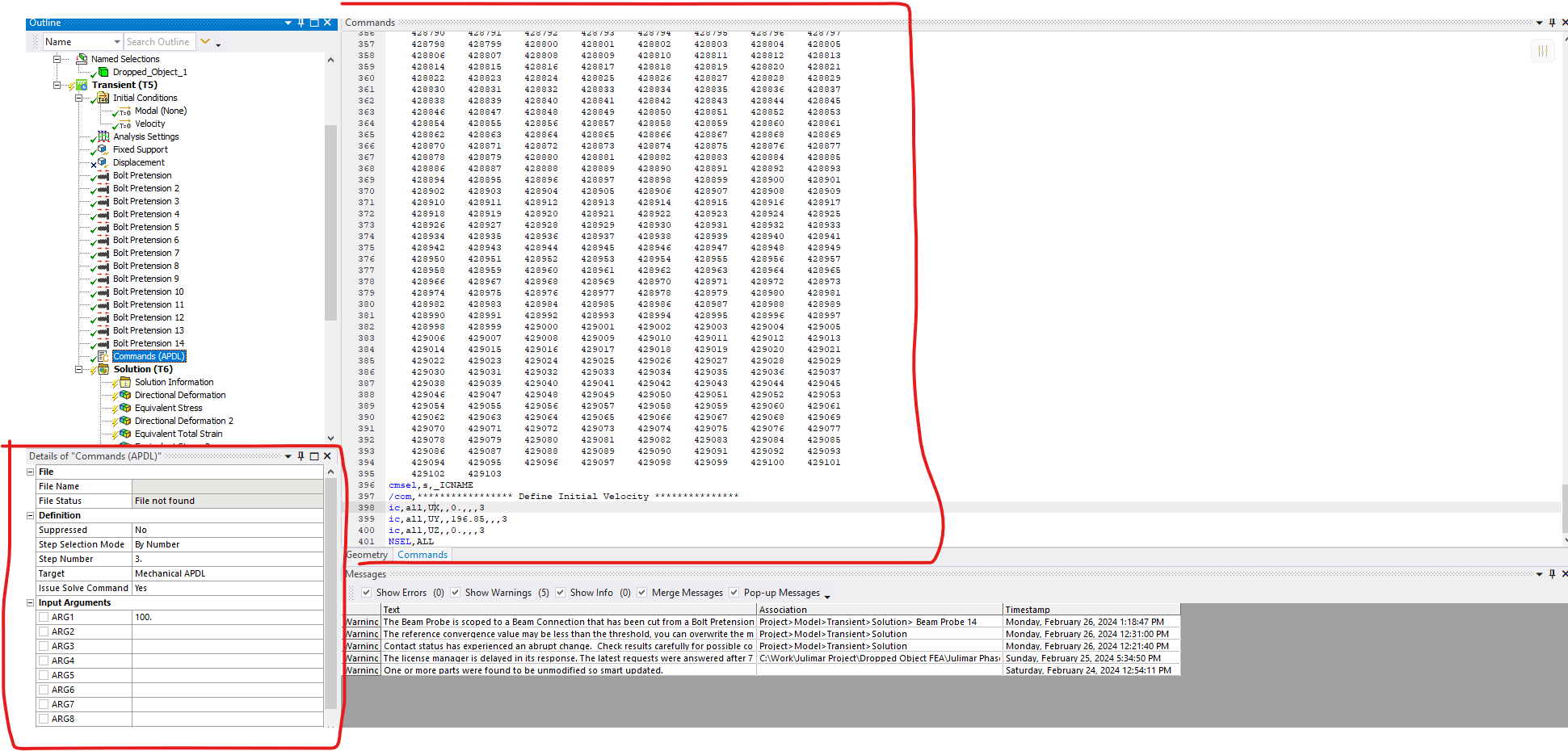
      VALUE is after the third comma. This is where the 196.85 goes, not after the fourth comma. This seems like a mistake in your code, however you found two commas in the original .dat file that Mechanical wrote out, which seems wrong. Please confirm what Mechanical writes out in the single step solution without bolt pretension.

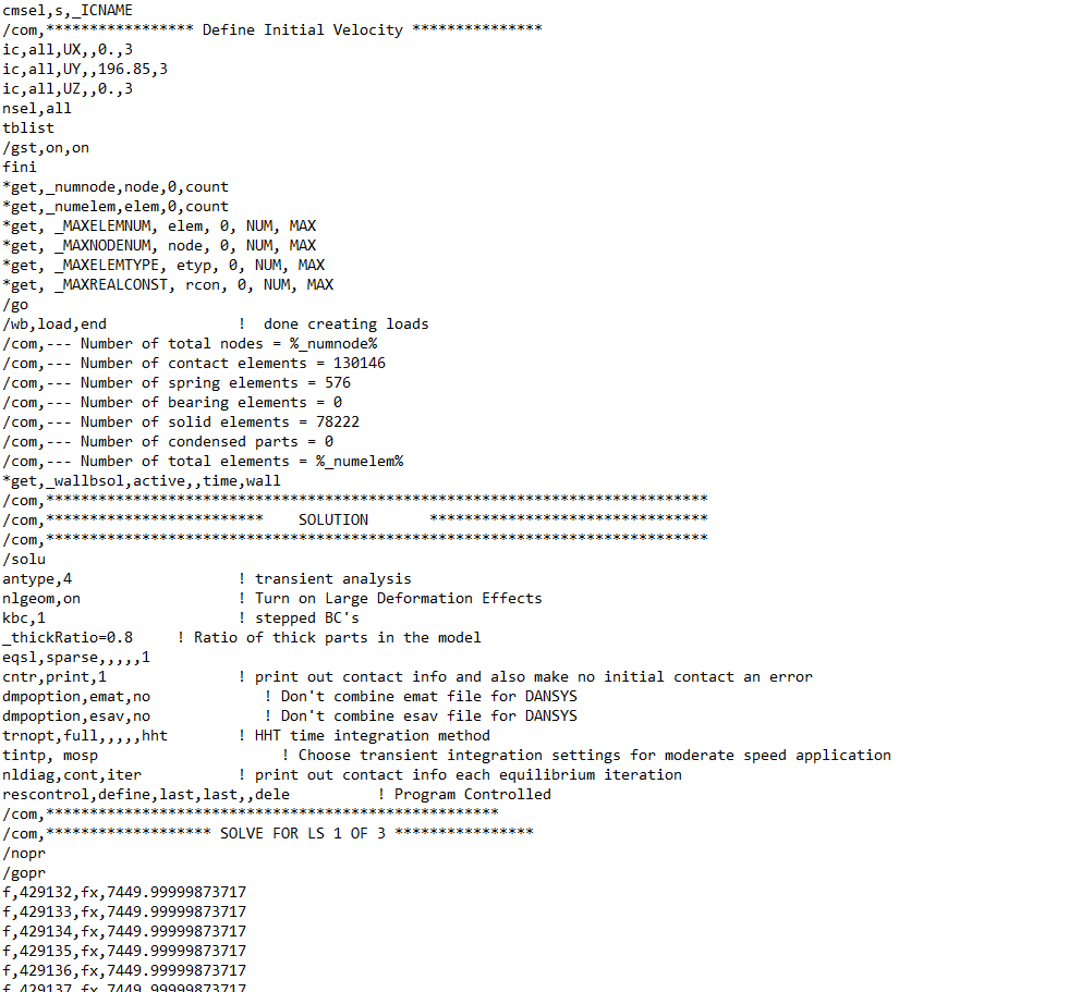
      The following line is what you could try.

      IC,N_Obj,VELY,196.85,,,,3

      I don’t think you need to specify VELX or VELZ because 0 is the default IC.

      Notice in the .dat file that there is a cmsel command above the IC commands. That is selecting a component so the IC commands can use ALL for the NODE. 

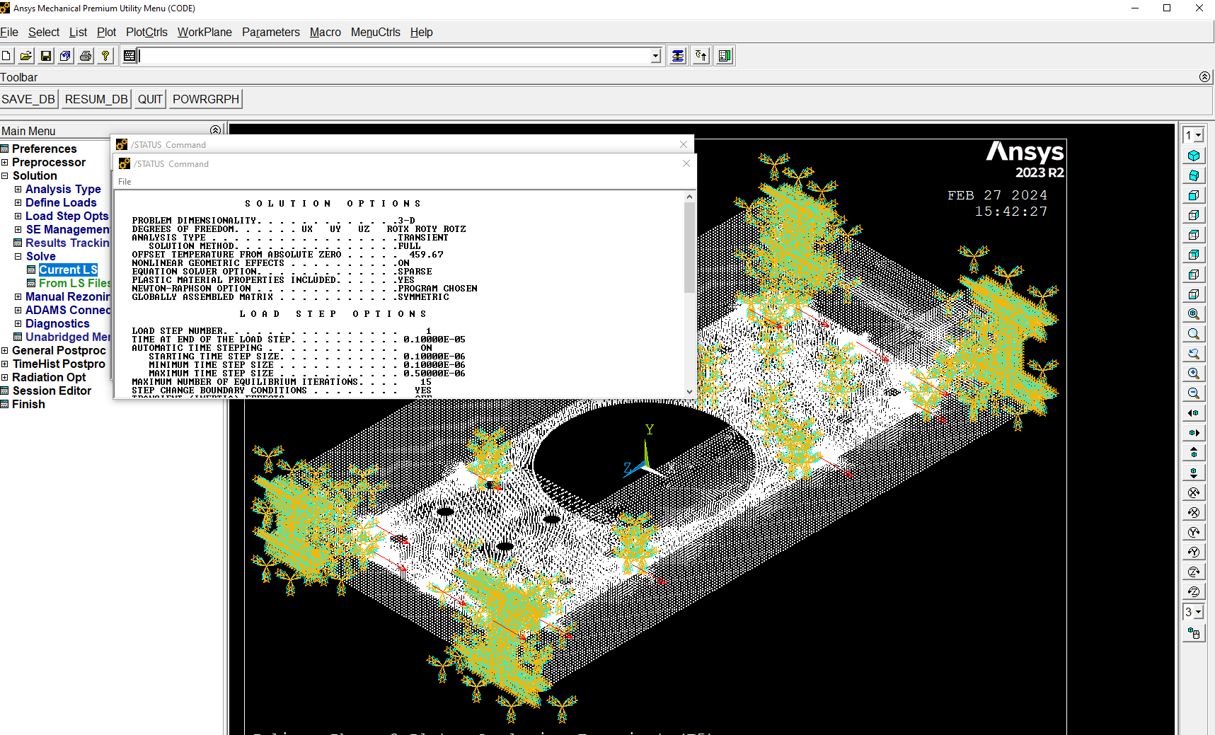
      Notice there are several lines below the IC commands. I don’t know if you need any of those in your Command Object.  This is why it can be easier to do minimal editing of the original .dat file and manually run the solver. Try following the IC command syntax as it is written in ANSYS Help and get the manual workflow working before you move on to a Command object workflow.

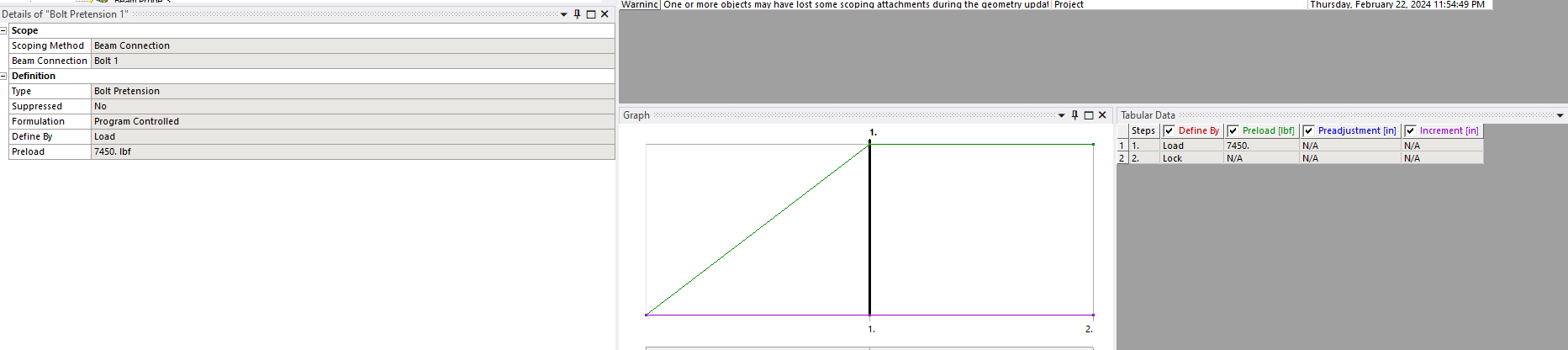
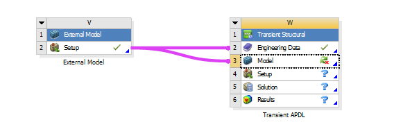
      As I mentioned before, there are two places to insert Command objects. Delete the Command object from the Solution branch, insert one under the Transient Structural branch and try the solve again with a repaired syntax.

    • Shady Alissa
      Subscriber


      I did try to run it in mechanical APDL however when I hit solve it automatically sets the solver to solve for load step 1 only. I cant seem to get it to solve for all 3 load steps?  I did try to set the load step from the load step opts to read the LS file but it says code 3 does not exist


    • peteroznewman
      Subscriber

      There are two items with similar names on the Windows Start Menu.

      Mechanical APDL is a Pre and Post Processor in the same way that Mechanical is a Pre and Post Processor.

      Mechanical APDL Product Launcher is a front end to submit jobs to the solver.

      Don’t use the first one, use the Product Launcher which looks like this:

      The Job Name is the name of the .dat file that you edited. Once you have selected that, click the Run button at the bottom.

    • peteroznewman
      Subscriber

      • Shady Alissa
        Subscriber

        Yes the product launcher is what I opened however when I run the dat file in APDL product launcher it doesnt complete the run. Editing the initital velocity to load step 3 might be preventing it from solving. 

    • peteroznewman
      Subscriber

      Look at the list of files in the directory where the solver ran.  Did you see solve.out?  Look at the last page for any errors.

      I would be interested to try this out with your model if you are willing to share the .wbpz file that is created when you use File > Archive in Workbench. Put the .wbpz file (not the .wbpj file) up on a file sharing site like Google Drive and reply with the link. Make sure to choose the option that anyone with the link can open the file.

    • Shady Alissa
      Subscriber

      Yes I am not sure why that is. I can run it in mechanical but not in APDL launcher.

      Here is the wbpz file as requested:

      https://drive.google.com/file/d/19MeEyqYyZmvsTvvRVyAgqLWVjLxUxL8M/view?usp=sharing

Viewing 23 reply threads
  • The topic ‘Nonlinear Impact Analysis with preloaded bolts using Transient Structural’ is closed to new replies.