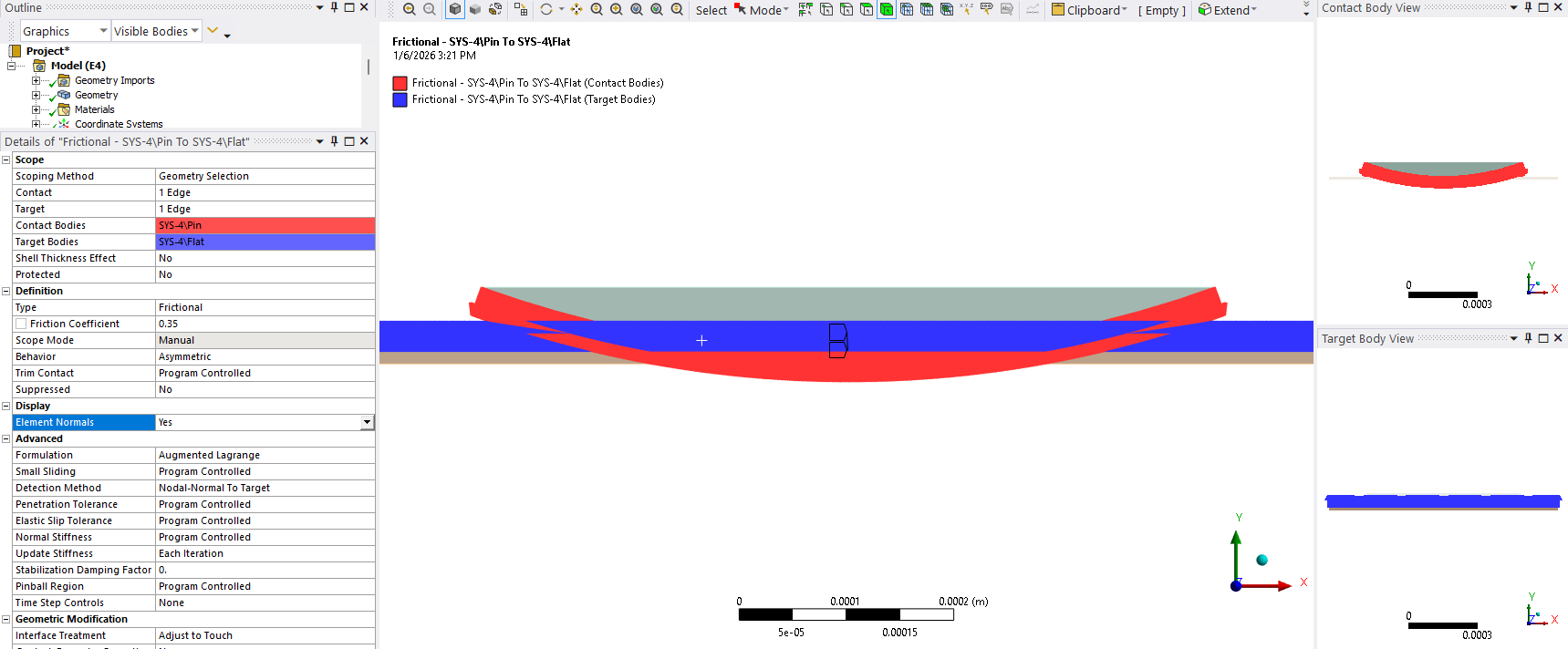
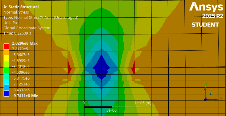
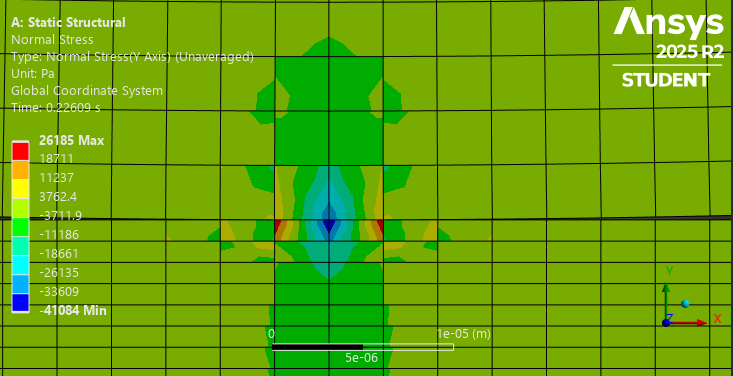
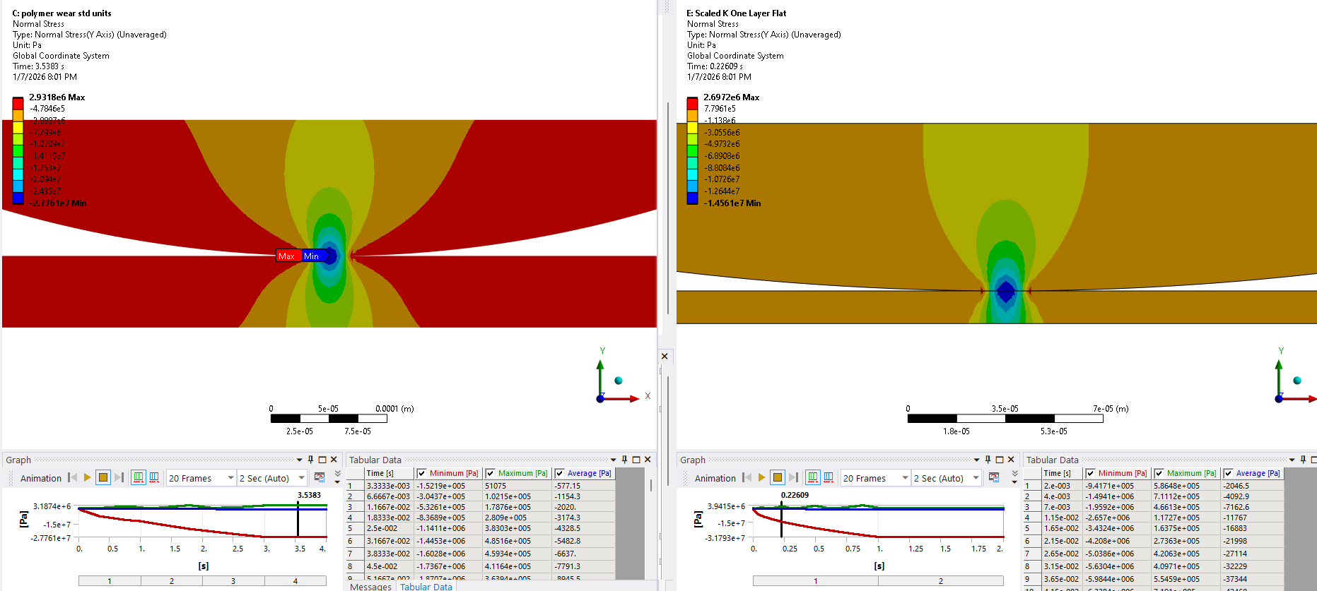
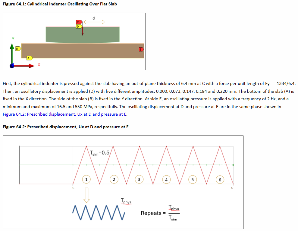
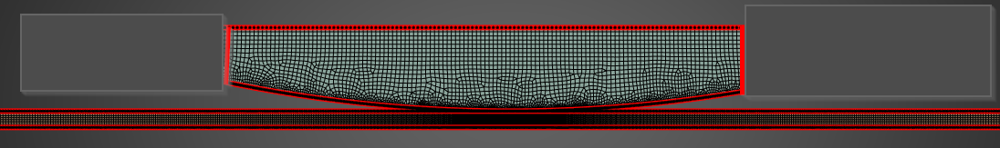
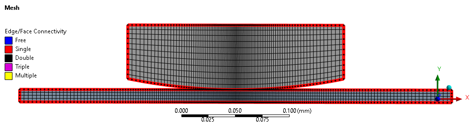
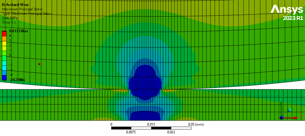
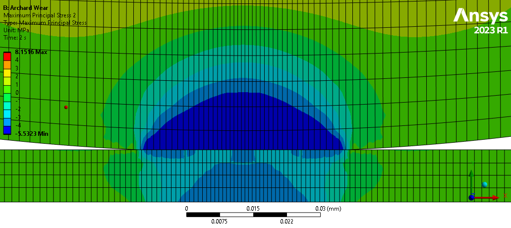
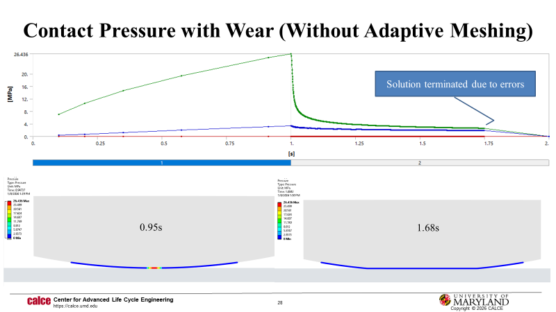
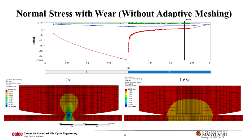
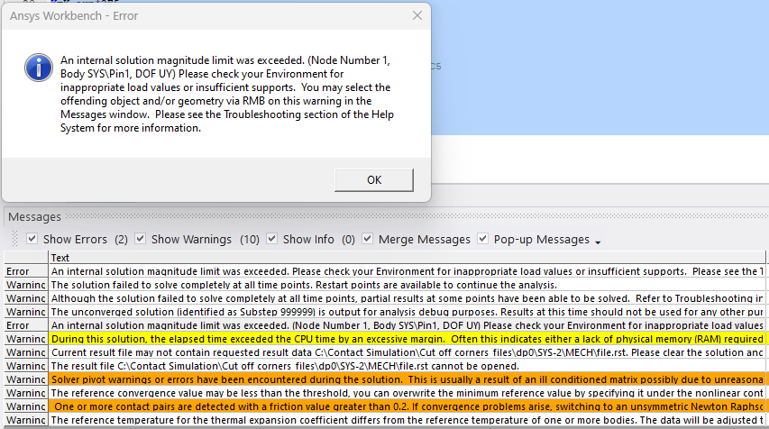
I am following this example here: (https://ansyshelp.ansys.com/public/account/secured?returnurl=///Views/Secured/corp/v242/en/wb_wbtec/WBtecwear.html). I am trying to simulate fretting wear for a polymer pin and a metal flat using a 2D Archard wear model. I have scaled the wear coefficient to simulate wear for 10 million cycles in 1s. Below are the commands for the asymmetric frictional contact (only pin wears, COF 0.35) and non-linear adaptive meshing. I was able to generate a stress contour when the wear is off, but the stress contour disappears for the step where wear is ON. The number of contacting elements stays the same, as no real movement is simulated, just the wear coefficient. The solution converges, but no change in mesh happens, so no change occurs in the volume of the bodies. Why can I not produce wear? Here is a graphic for the model: https://imgur.com/a/XBmTeSH

keyo,cid,5,1 !KEYOPT(5) = 1 is set to close the gap with an auto contact surface offset (CNOF)
keyo,cid,10,2 !KEYOPT(10) = 2 is set to perform a contact stiffness update each iteration
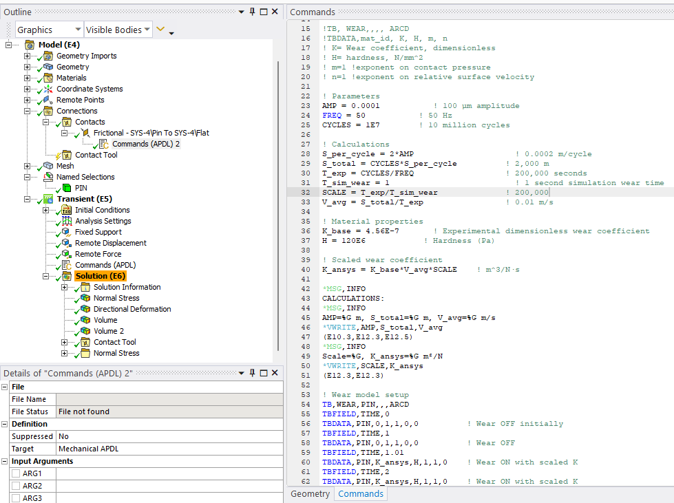
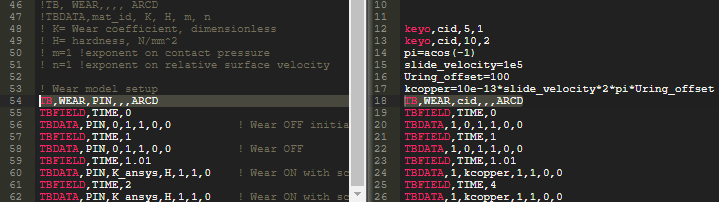
! Wear model setup
TB,WEAR,PIN,,,ARCD
TBFIELD,TIME,0
TBDATA,PIN,0,1,1,0,0 ! Wear OFF initially
TBFIELD,TIME,1
TBDATA,PIN,0,1,1,0,0 ! Wear OFF
TBFIELD,TIME,1.01
TBDATA,PIN,K_ansys,H,1,1,0 ! Wear ON with scaled K
TBFIELD,TIME,2
TBDATA,PIN,K_ansys,H,1,1,0 ! Wear ON with scaled K
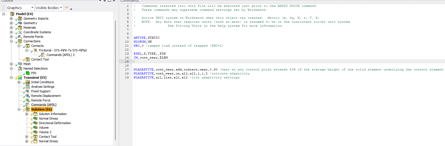
ANTYPE,STATIC
NLGEOM,ON
KBC,0 !ramped load instead of stepped (KBC=1)
!ESEL,S,TYPE,,PIN
!CM,wear,ELEM
!*GET,numelem,CM,cont_wear,ELEM ! Returns number of elements in component
NLADAPTIVE,all,add,contact,wear,0.50 !wear at any contact point exceeds 50% of the average height of the solid element underlying the contact element
NLADAPTIVE,all,on,all,all,1,,2 !activate adaptivity
NLADAPTIVE,all,list,all,all !list adaptivity settings
Listing the parameter just in case:
! Parameters
AMP = 0.0001 ! 100 µm amplitude
FREQ = 50 ! 50 Hz
CYCLES = 1E7 ! 10 million cycles
! Calculations
S_per_cycle = 2AMP ! 0.0002 m/cycle
S_total = CYCLES*S_per_cycle ! 2,000 m
T_exp = CYCLES / FREQ ! 200,000 seconds
T_sim_wear = 1 ! 1 second simulation wear time
SCALE = T_exp / T_sim_wear ! 200,000
V_avg = S_total / T_exp ! 0.01 m/s
! Material properties
K_base = 4.56E-7 ! Experimental dimensionless wear coefficient
H = 120E6 ! Hardness (Pa)
! Scaled wear coefficient
K_ansys = K_base*V_avg*SCALE ! m^3/N·s
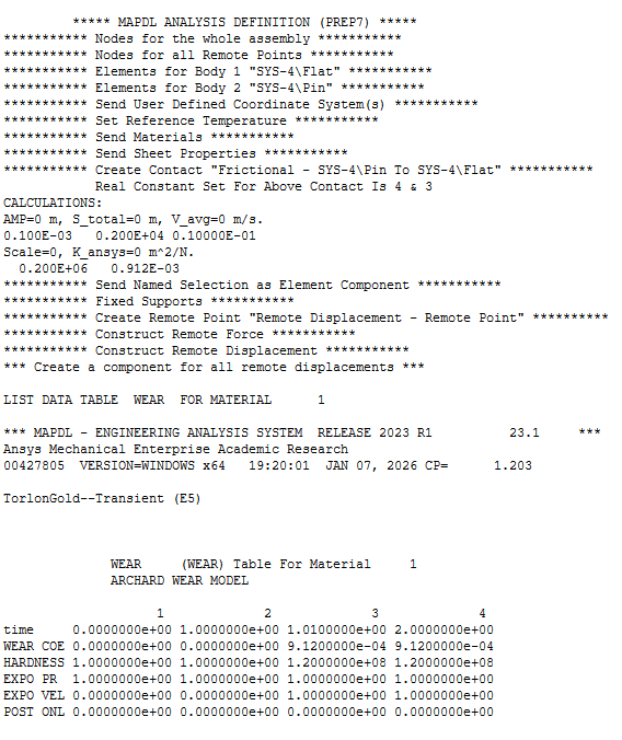
*MSG,INFO
CALCULATIONS:
*MSG,INFO
AMP=%G m, S_total=%G m, V_avg=%G m/s
*VWRITE,AMP,S_total,V_avg
(E10.3,E12.3,E12.5)
*MSG,INFO
Scale=%G, K_ansys=%G m²/N
*VWRITE,SCALE,K_ansys
(E12.3,E12.3)
!TBDATA,mat_id, K, H, m, n
! K= Wear coefficient, dimensionless
! H= hardness, N/m^2
! m=1 !exponent on contact pressure
! n=1 !exponent on relative surface velocity