-
-
July 25, 2023 at 10:43 am
Waruna Maddumage
Subscriber
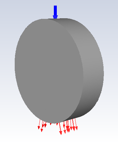
In Fluent, I am currently working on a heat transfer case involving two phases: coolant oil and air. The simulation includes the spraying of oil onto a metal geometry using a jet nozzle. The metal geometry has a heat source of 24 W, causing it to heat up to an average temperature of 90°C. The coolant oil is injected into the domain at a temperature of 40°C, and the surrounding area is filled with air at 20°C. To replicate the lab experimental setup accurately, I have extended the model to encompass a very large surrounding area around the metal geometry. The intention behind this is to account for the effects of natural convection cooling.ÂFor the simulation, I have set up the following boundary conditions: a velocity inlet with a volume fraction of 1 for the oil, a pressure outlet with a volume fraction of 1 for the backflow air at 20°C. all other boundaries are adiabatic.ÂÂThe simulation is conducted in a steady-state manner, and I have utilized the SST k-omega turbulence model.  The multiphase model is VOF Implicit with implicit body force, VOF boundary is dispersed. The mesh incorporates 10 boundary layers, and all walls have a y+ value below 4, while the walls of the metal geometry have a y+ value below 1.Â
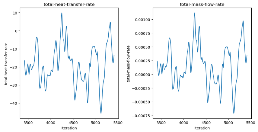
Currently, when calculating the total heat transfer imbalance, which considers the contributions from the inlet, outlet, and energy source, I am obtaining a value of -11W. I am guessing this is because the cooling effect from the large surrounding air domain is not calculated here.ÂÂMy question is whether my assumption is correct, and if so, how can I incorporate the natural convection heat transfer from the surrounding air into the energy transfer imbalance calculation? -
July 25, 2023 at 12:01 pm
Rob
Forum ModeratorYou also want to add in the heat lost from any external boundaries. Note, VOF isn't recommended for sprays unless you're resolving all the droplets so please review the documentation on the model.Â
-
July 25, 2023 at 12:47 pm
Waruna Maddumage
SubscriberHi Rob,Â
Thanks for the quick reply. All my other external boundaries are adiabatic, thus not affecting the heat transfer imbalance. Also, I am not modelling a spray. It's a low-velocity oil jet. The droplet formation is low. I reviewed the documentation and talked with an ANSYS expert in the last UK conference you guys had, I think VOF should be able to handle my case.Â
Can I please bring your attention to my original question? My surrounding domain is large (filled with air) and will start cooling the metal geometry through natural convection. Isn't this the reason for the negative net heat transfer imbalance?Â
Thanks,
Waruna
-
-
July 25, 2023 at 1:11 pm
Rob
Forum ModeratorThe air will warm up, so it's possible your missing heat is still in the domain if the model is transient.
-
July 25, 2023 at 5:35 pm
Waruna Maddumage
SubscriberMy model is steady state.
Also in my model, I don't have an air input. Will it help if I model a pressure inlet only for air in addition to the velocity inlet for oil? I'll keep the pressure outlet with the backflow (volume fraction air 1) as it is. Will this help for natural convection air circulation and balance my model?Â
Any suggestions to resolve this will really help.
Thanks.
Waruna
-
-
July 26, 2023 at 7:50 am
Rob
Forum ModeratorIf you're adding mass to the domain where does the air go? How are the residuals looking?Â
-
August 14, 2023 at 9:02 am
Waruna Maddumage
SubscriberHi Rob,Â
Below is a picture of the domain. I'm sorry I can't show the metal geometry inside the domain since I don't have the approval to share on a public platform. But inside the grey cylinder is a motor end winding geometry. Input is a jet nozzle (input volume fraction oil = 1). The outlet is at the bottom where the air inside and oil go out. I have enabled reverse flow at the outlet as well (air volume fraction = 1).
Answer your second question. My energy residuals are below e-8. All the other residuals are below e-3 except for continuity and k. Continuity fluctuates around 1e-1 and k is below 1e-2.Â
Also, I plotted the total heat transfer rate throughout the simulation. It changes a lot. Values fluctuate between to 8 to -12W (heat source = 23W). But my temperature readings are pretty stable they very between 3 degrees.Â
Really appreciate any advise you can give on this.Â
-
-
August 14, 2023 at 10:45 am
Rob
Forum ModeratorOK, continuity will be the key here. Add a volume monitor of VOF mass in the domain and see how that looks. I suspect it'll not be a flat line, and then look at the mass of oil in & oil out as two extra monitors. If you take the mass variation of oil, and know the heat capacity what sort of temperature change would you expect?Â
Â
-
August 14, 2023 at 11:14 am
Waruna Maddumage
SubscriberHi Rob,Â
Thanks for the quick reply. I haven't used the exact monitors you mentioned and I will start a simulation with these today. In the meantime, I can show you a few similar monitors I have been using to check continuity.
All the graphs below are for the last 2000 iterations.Â
- total-heat-transfer-rate (W) - does not take the heat source (23W) to account
- total-mass-flow-rate (kg/s) - All input minus output fluid (oil and air), maximum mass imbalance is 8%Â
- avg-vf-oil-in-fluid -Â volume average of the volume fraction of oil in the fluid domain
- winding-temp (k) - Area weighted average of the winding temperature Â
As you can see the temperature value does not change a lot. I do not fully understand this part of your answer "If you take the mass variation of oil, and know the heat capacity what sort of temperature change would you expect? "
-
-
August 14, 2023 at 11:44 am
Rob
Forum ModeratorIf the heat source is 23W I'd expect the balance to be around -23W as more heat leaves than enters through the boundaries. That more-or-less ties up with the graphs.Â
If you check the (total imbalance * cp) what sort of values do you come out with? Temperature may not change much if most of the heat finishes up in the oil as it'll have a relatively high heat capacity compared to air.Â
The domain oil fraction isn't looking to be entirely at equilibrium, but I appreciate this is shorter plot than the whole simulation.Â
-
August 14, 2023 at 12:12 pm
Waruna Maddumage
SubscriberHi Rob,Â
Yes, I would expect it to balance around -23W as well. But as you can see the values deviate a lot.Â
The specific heat (Cp) of oil is around 1600 J/kg k. At 5000 iteration point, total mass imbalance * Cp = 0.6522. The total heat transfer rate imbalance at this point is 12.5 W (net value considering the heat source).Â
You are correct about the domain oil fraction. It does not look like it's at equilibrium. But since the temperature change is small it doesn't seem to affect much.Â
-
-
August 14, 2023 at 12:30 pm
Rob
Forum ModeratorIt's not an unreasonable dT compared to the overal variation in the domain. Especially as there looks to be slowly increasing amount of liquid in the volume.Â
I suspect it's mostly convergence.Â
-
August 14, 2023 at 12:40 pm
Waruna Maddumage
SubscriberDo you have any advice to improve the convergence? Or at least any limits for monitors I can use to say confidently the solution is converged.Â
My Mesh has a min orthogonal quality of 0.15 and 99% of cells have an aspect ratio less than 100 (a few cells around 200). My model is around 30M cells now. Since it is not the best Mesh, could this be a problem as well for poor convergence?Â
-
-
August 14, 2023 at 1:30 pm
Rob
Forum ModeratorHigh aspect ratio and VOF tend not to mix well, but other than going transient to pick up wave/ripples etc it's probably about there.Â
Note cell count, y+ = 1 and cell quality don't always mean you have a good mesh. You need to ensure you resolve all of the gradients, ie have good resolution where it's interesting.Â
-
August 14, 2023 at 1:36 pm
Waruna Maddumage
SubscriberThanks a lot for the advice,
What kind of aspect ratio should I aim for?
As for ensuring a good resolution, do you mean looking at mesh independence?Â
-
August 14, 2023 at 1:53 pm
Rob
Forum ModeratorMesh independence, yes, but if you plot contours with node values off you can usually get a good idea if you're resolving everything (phase, velocity, temperature & pressure) sufficiently.Â
Apect ratio is a difficult one. If VOF is flowing along the cells and you have ripples/waves then it needs to be fairly low (you need to resolve the flow along the wall as much as you do towards the wall). If there's no VOF free surface then the usual rules apply.Â
-
- The topic ‘Negative total heat transfer imbalance’ is closed to new replies.
- air flow in and out of computer case
- Varying Bond model parameters to mimic soil particle cohesion/stiction
- Eroded Mass due to Erosion of Soil Particles by Fluids
- I am doing a corona simulation. But particles are not spreading.
- Centrifugal Fan Analysis for Determination of Characteristic Curve
- Guidance needed for Conjugate Heat Transfer Analysis for a 3s3p Li-ion Battery
- Issue to compile a UDF in ANSYS Fluent
- JACOBI Convergence Issue in ANSYS AQWA
- affinity not set
- Resuming SAG Mill Simulation with New Particle Batch in Rocky
-
4167
-
1487
-
1358
-
1188
-
1021
© 2025 Copyright ANSYS, Inc. All rights reserved.


