-
-
March 28, 2024 at 12:37 pm
Anunda Chuenlerssakul
SubscriberHi all,
I'm trying to simulate the negative stiffness graph in my interior permanent magnet motor. The result should be linear as the force should be increase when the PM is near the stator teeth. I use the rotor base material as epoxy and I also changing the material to steel but the behavior is still the same. Could anyone help on this point?
Thank you so much.
Anunda
-
April 2, 2024 at 4:09 pm
wrbulat
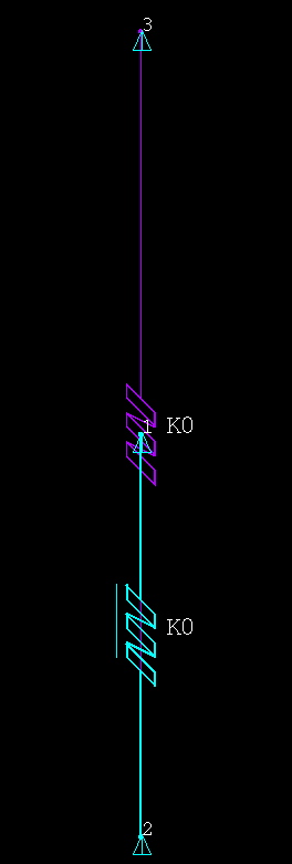
Ansys EmployeeI'm not sure this is exactly what you're asking for, but I found this old MAPDL input file that uses two spring elements (COMBIN14 and COMBIN39) to posit nonlinear negative stiffness between two nodes (to mimic net magnetic force versus separation):
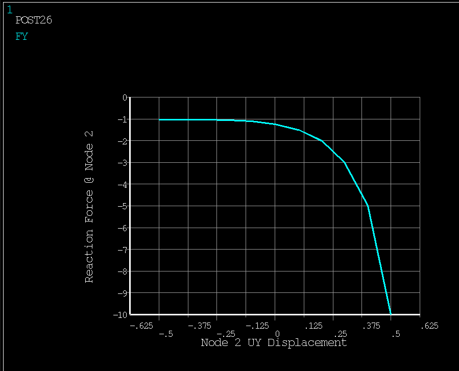
fini/cle/sys,del test_neg_K_05*.png/fil,test_neg_K_05/pnu,node,1/pnu,type,1/tri,lbot/esha,1/ics,1,5/pbc,u,1C***********************************C*** MODELC***********************************/prep7n,1,,1 ! NODESn,2n,3,,2et,1,39,0,0,2 ! NONLINEAR SPRING (COMBIN39) ATTRIBUTESr,1, -0.5,10-1.25, -0.4,5-1.25, -0.3,3-1.25rmore, -0.2,2-1.25, -0.1,1.5-1.25, 0,1.25-1.25rmore, 0.1,1.10-1.25, 0.2,1.05-1.25, 0.3,1.03-1.25rmore, 0.4,1.02-1.25, 0.5,1.015-1.25et,2,14,,,2 ! LINEAR SPRING (COMBIN14) ATTRIBUTESr,2,1.25/50type,1 ! SINGLE NONLINEAR COMBIN39 ELEMENTreal,1e,2,1type,2 ! SINGLE LINEAR COMBIN14 ELEMENTreal,2e,3,2d,1,uy ! BOUNDARY CONDITIONSd,3,uy,50fini/solu ! SOLVEauto,offoutr,all,allnsub,1d,2,uy,-0.5solvnsub,10d,2,uy,0.5solvfinieplo/sho,png $eplo $/sho,close $/wait,2/post26 ! VERIFY FORCE-DEFLECTIONnsol,2,2,uyxvar,2rfor,3,2,fy/axl,x,Node 2 UY Displacement/axl,y,Reaction Force @ Node 2!/yra,0,10plva,3/sho,png $plva,3 $/sho,close $/wait,2Note that as node 2 at the bottom of the two element model is moved upward, the reaction force becomes increasingly negative (the springs are pulling upward on node 2 with increasing force as node 2 gets closer to node 3).
In Mechanical, you would have to include commands like these in a command object, maybe written in such a way that the springs are attached to remote point nodes scoped to surfaces.
--Bill
-
- The topic ‘Negative stiffness in x-position between PM and steel stator’ is closed to new replies.


-
4949
-
1639
-
1386
-
1242
-
1021

© 2026 Copyright ANSYS, Inc. All rights reserved.


