
-
-
November 30, 2021 at 6:45 am
Ranjan13
SubscriberDear all!
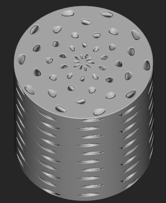
I have a cylindrical structure as shown in the figure below:
November 30, 2021 at 7:09 amErKo
Ansys EmployeeHi
Use just normal symmetry in the the two quarter faces which should have an axis perpendicular to them - or just fix that displacement along the normal of the face as shown in the video below.
See here for sym.:
Cyclic symmetry you need to have certain mesh (same actually - and using some ways to copy the mesh between the faces) on the cyclic faces which you do not have since it is an import.
All the best
November 30, 2021 at 8:24 amSubscriberHi Erik Thanks for the prompt response! I tried to implement the normal symmetry in my model. But I am facing a problem in selecting the face from my lattice structure using both Geometry and Named Selection options. Using the face selection feature in the Geometry selection, it is selecting the whole volume instead of a face. The Named Selection option is not giving me the list of the faces from the structure which I imported from nTopology for applying boundary conditions (As shown in the below image):
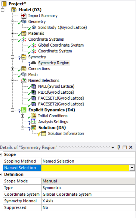 Could you please tell me how can I select the faces from the gyroid lattice? I have imported the lattice as an Abaqus input file from nTopology along with the name selected faces.
Thanks a lot in advance!
Regards Ranjan
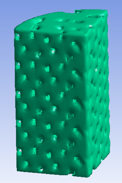
November 30, 2021 at 8:28 amAnsys EmployeeCan you please show your imported lattice model inside the mechanical
UI (just want to see how it looks) and also show the named selection FACESET1 and 2.
thank you
Erik
November 30, 2021 at 9:20 amSubscriberHi Erik Here it is:
Imported model
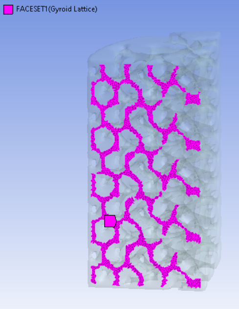
 FACESET 1:
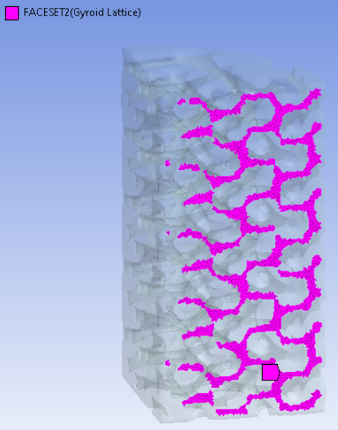
 FACESET 2:
 Thanks a lot!
Regards Ranjan
November 30, 2021 at 9:41 amAnsys EmployeeNo worries.
To be honest these part or at least the named selections are not very similar with each (different amount of nodes in each face and distribution) other which one would expect, so something is strange - in the software you use to generate the lattices I would start with these faces being completely planar so it does not curve them, because a symmetry plan should be flat to make life easy. Once this is done (flat symmetry faces) then:
So try to add a Displacement boundary condition (BC) as shown in the image below, and then restrain the displacement (set it to 0) in the direction perpendicular to these symmetry faces (just as shown in the video above in the previous post). You need like in the video of course to have 2 Displacement BC, one for each symmetry plane.

All the best
Erik
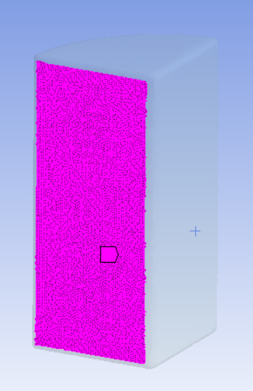
November 30, 2021 at 2:16 pmSubscriberHi Erik I did create a more planar surface in the external model and imported it to Ansys mechanical for applying the symmetry conditions. But unfortunately, it is still not showing in the drop-down list under the named selection feature. Please find below the surfaces I imported from nTopology:
FACESET 1:
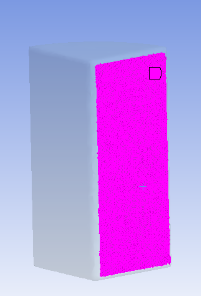
 FACESET 2:
 I am using version 2021 R2 on my laptop. I have also checked in my friend's laptop (version 18.1), but still facing the same problem.
Thanks a lot!
Regards Ranjan
November 30, 2021 at 2:21 pmAnsys Employee
Please read through my post carefully - we can not use symmetry so do this instead which is equivalent to a symmetry condition:
So add a Displacement boundary condition (BC) as shown in the image below, and then restrain the displacement (set it to 0) in the direction perpendicular to these symmetry faces (just as shown in the video above in the previous post). Finally you need to have 2 Displacement BC, one for each symmetry plane.
So use displacement
Also search the internet to understand what a symmetry BC is (just restrains degrees of freedom that are/move perpendicular to the symmetry plane - so for 3D elements either UX,UY, or UZ) - see this video for a simple example:
Thank you
Erik
November 30, 2021 at 3:24 pmSubscriberHi Erik Yeah understood it now. Thanks a lot for the guidance! By using displacement in place of symmetry the only drawback I think is we can't see the full model after getting the results for the quarter model. Please let me know if there is a way to see the full model with all the results.
Thanks a lot in advance!
Regards Ranjan
November 30, 2021 at 3:35 pmAnsys EmployeeHi
That is very good.
Yes, we can not see the full model in the results with displacement (as we said though symmetry on nodal named selections does not work with the imported external model).
All the best
Erik
November 30, 2021 at 4:18 pmSubscriberThanks a lot, Erik for your valuable time and guidance!!
Best Regards Ranjan
Viewing 10 reply threads- The topic ‘Need suggestions regarding the explicit dynamic analysis’ is closed to new replies.
Innovation Space Trending discussions
 Top Contributors
-
peteroznewman
 5799
5799 -
scabo
 1906
1906 -
Dennis Chen
 1419
1419 -
javat33489
 1305
1305 -
Shyam Prasad V Atri
1021
Top Rated Tags
© 2026 Copyright ANSYS, Inc. All rights reserved.
Ansys does not support the usage of unauthorized Ansys software. Please visit www.ansys.com to obtain an official distribution.
-


The Ansys Learning Forum is a public forum. You are prohibited from providing (i) information that is confidential to You, your employer, or any third party, (ii) Personal Data or individually identifiable health information, (iii) any information that is U.S. Government Classified, Controlled Unclassified Information, International Traffic in Arms Regulators (ITAR) or Export Administration Regulators (EAR) controlled or otherwise have been determined by the United States Government or by a foreign government to require protection against unauthorized disclosure for reasons of national security, or (iv) topics or information restricted by the People's Republic of China data protection and privacy laws.
