TAGGED: antenna, lumped-rlc, unit-cell
-
-
March 4, 2024 at 11:16 am
Aman Saini
SubscriberHi everyone.
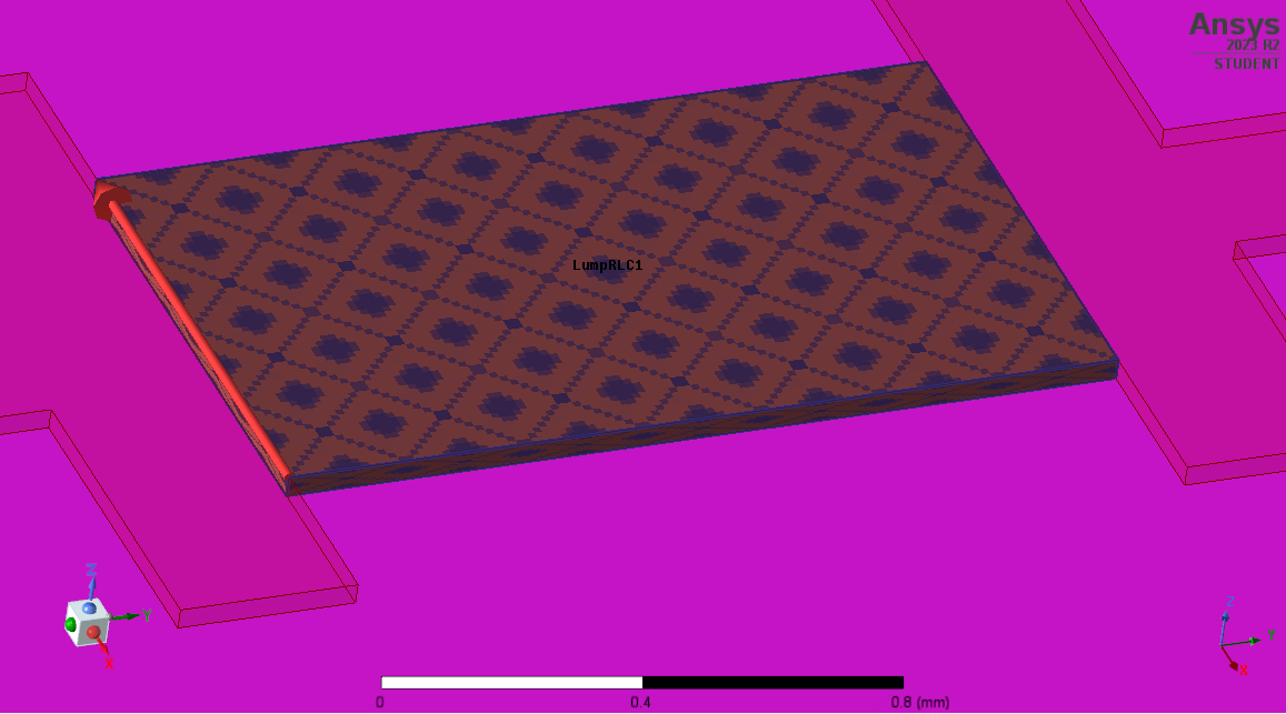
I am trying to simulate a unit-cell in HFSS and I want to model a varactor diode in the simulation. Currently, I am using a copper-box structure assigned as Lumped RLC with length and width in accordance to the datasheet. I have taken height of the box to be equal to the copper height (which is the height of the copper lines between which varactor is needed to be connected). I have attached the image of the model for reference. I want to know, if this is the correct way to model the varactor diode (I also tried using rectangular sheet assigned as a Lumped RLC but the results showed no variations with variation in lumped capacitance).
This kind of modelling gives me a warning while validation: "Solving inside a solid with high conductivity may require a large mesh"

-
March 22, 2024 at 2:34 pm
Praneeth
Bbp_moderatorHi Aman,
Thank you for reaching out to the Ansys learning forum. Your patience is much appreciated.
Please go through the following suggestions if you are still trying for the solution:
- The component you are trying to model as RLC should be implemented as a 2D sheet instead of as 3D object and assign lumped RLC boundary. Also it looks like the current flow line is not correctly assigned in your model. If you are new to using lumped RLC boundary, then please go through the "Assigning Lumped RLC Boundaries" section of the HFSS help document.
- If you are implementing the diode as an equivalent circuit, then it may not be the accurate way as the diode switching may not be correctly modeled with this approach. Instead, you can implement the circuit element approach using the s-parameters of the varactor diode.
Best regards,
Praneeth.
-
- The topic ‘Need help with modelling a varactor diode for unit cell simulation in HFSS.’ is closed to new replies.


-
3597
-
1258
-
1107
-
1068
-
953

© 2025 Copyright ANSYS, Inc. All rights reserved.


