We have an exciting announcement about badges coming in May 2025. Until then, we will temporarily stop issuing new badges for course completions and certifications. However, all completions will be recorded and fulfilled after May 2025.
General Mechanical

General Mechanical

Topics related to Mechanical Enterprise, Motion, Additive Print and more.

Necking in tensile specimen

    • tamonash.jana
      Subscriber

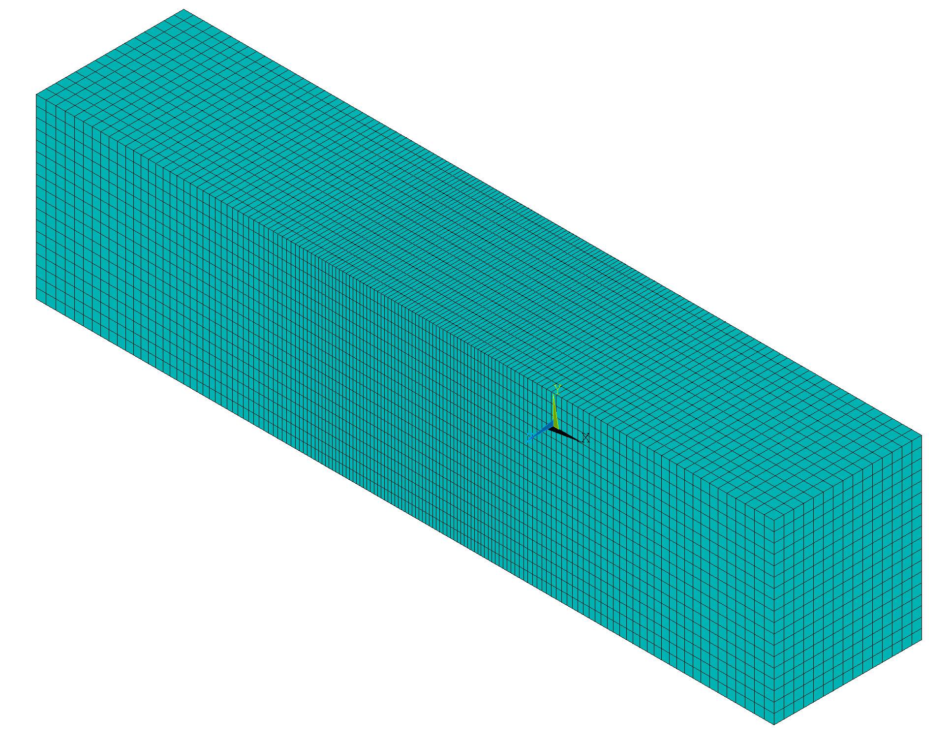
      I am simulating a uniaxial tensile test on a stainless steel specimen using ANSYS APDL under static structural analysis. The analysis is conducted only on the gauge section of the specimen, and the loading is applied in a displacement-controlled manner. The material’s post-elastic behaviour is modelled using the MISO hardening model, with parameters adopted from Soares et al. (https://doi.org/10.1590/1980-5373-MR-2016-0932). No explicit failure or damage model has been incorporated.

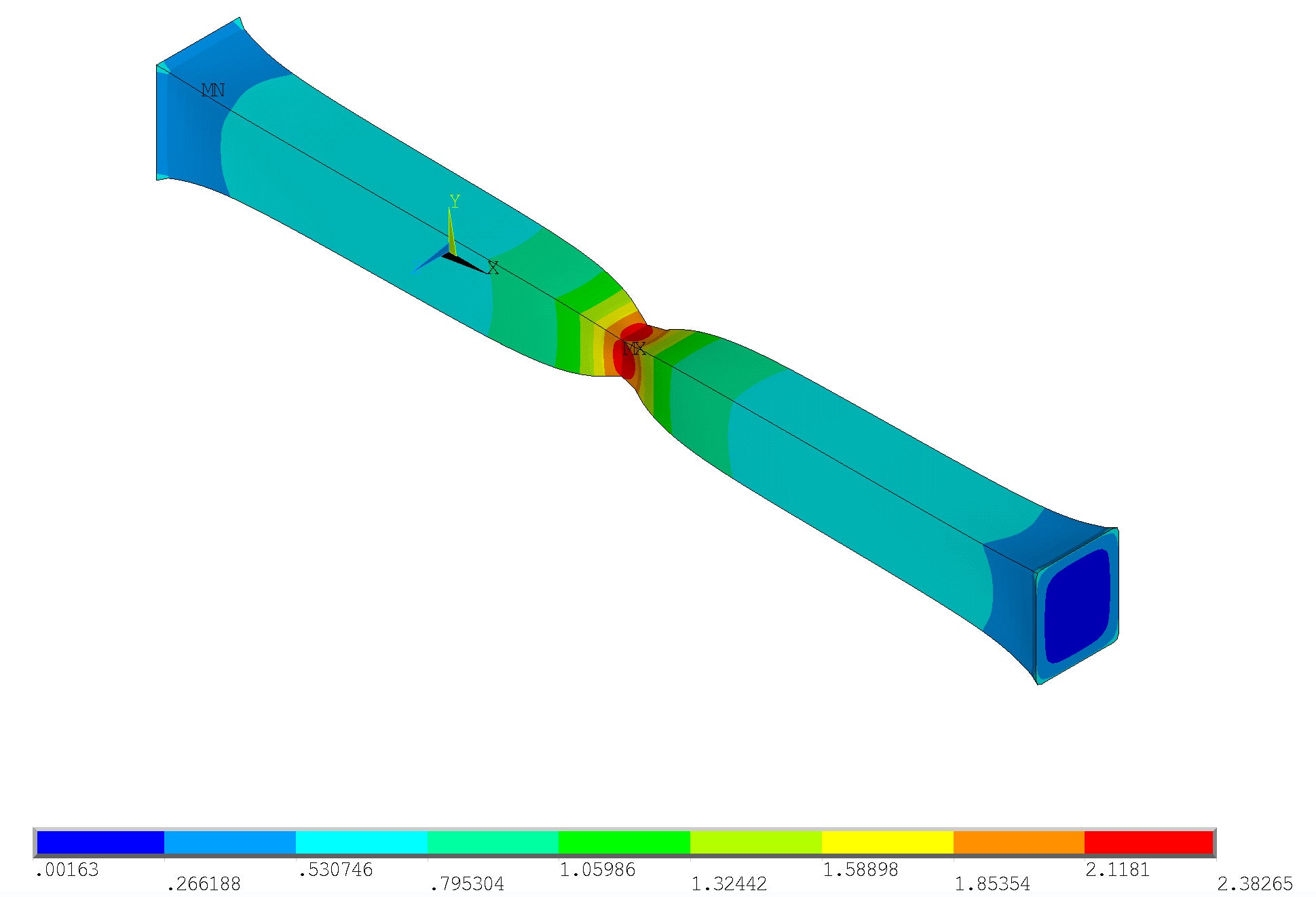
      However, beyond a certain applied displacement, I observe a drop in the reaction force and the onset of necking, which consistently initiates at the centre of the gauge length, despite no predefined geometric or material imperfection in that region.

      1. What is the underlying reason for the observed drop in load and the spontaneous onset of necking in the simulation?

      2. Why does necking localize specifically at the center, even though no constraints or imperfections are defined there?

      3. How can I extend the strain-hardening portion of the stress–strain curve to delay necking?

      4. Additionally, what is the best practice to introduce necking manually at a specific location and under a desired loading level (e.g., by geometric imperfection or localized softening)?

      Any guidance on improving the physical realism of the simulation or controlling necking behaviour would be greatly appreciated.


    • peteroznewman
      Subscriber
      1. When plastic strain occurs, it is essentially an incompressible flow of material, meaning there is a constant volume. The length is increasing so the cross-sectional area is decreasing to maintain a constant volume.  Since the material is on the flatter part of the stress-strain curve, the stress is not increasing fast enough to compensate for the reduction in cross-sectional area, therefore the reaction force falls.
      2. Necking an occur at unpredictiable locations along the gage length for simulations without any defects. If you remeshed with tet elements, the necking location would probably be elsewhere
      3. If all the stress values in the MISO table are increased, the onset of necking will occur at a higher reaction force.
      4. Simplest way to induce necking at a specific location is to introduce a notch in the side of the specimen.

      Here are two relevant discussions:

      https://innovationspace.ansys.com/forum/forums/topic/simulation-of-a-tensile-test-to-validate-material-properties/

      https://innovationspace.ansys.com/forum/forums/topic/tensile-test-of-al-2024-t4-to-calculate-ultimate-and-yield-stress/

    • Armin
      Ansys Employee

      Adding to Peter's points, consider looking up online the 'Considère criterion'. This is a mathematical condition used to predict the onset of necking in materials subjected to tensile stress. The criterion identifies the point at which the rate of strain hardening becomes less than the flow stress, indicating the onset of necking."

Viewing 2 reply threads
  • You must be logged in to reply to this topic.