TAGGED: #fluent-#ansys, meshing
-
-
January 30, 2024 at 6:05 pm
adave12
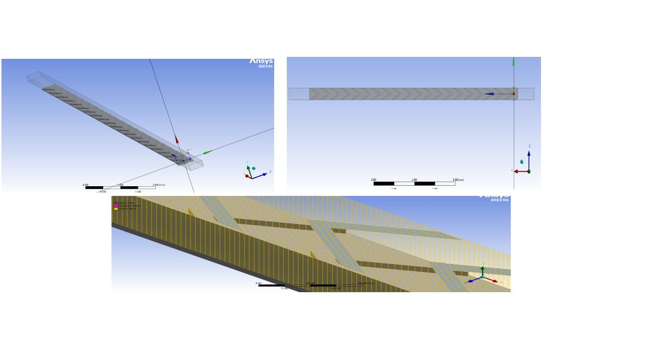
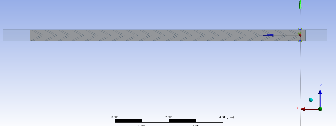
Subscriber Hello everyone, I have been trying to mesh a microchannel with some flow promoters using multizone mesh. I have tried to use some edge sizing and splitting some edges on the flow promoters , however there is still an issue with high skewness and low orthogonal quality. I have also tried using inflation layers , however that has turned out to be a bade decision . I was hoping if I could receive an understanding of where I am going wrong .
-
January 31, 2024 at 12:08 pm
Aniket
Forum ModeratorIt seems like your geometry is repeating, can it be possible to mesh a single section of it and later use periodic boundary conditions (in case the loads are periodic) or use model assembly to assemble the required mesh in the model?
This way you will have to debug only a small section. Once you have successfully debugged this small section, you can simply extrapolate those settings for the larger model.
Also, pay close attention to the error messages received, and right-click on them to check if any geometry is highlighted as problematic.
Finally, use local sizing only on the source faces, (but also try not to over constrain them) to control the mesh quality and size.
-Aniket
-
January 31, 2024 at 1:33 pm
adave12
SubscriberI actually did try meshing for a smaller sized domain and I did not have any issues with it . In fact the larger domain or the full sized domain was meshed at a particular element size and it fails for any other size. I tried to slice the whole domain into two sections and apply Multizone meshing. This process did not work.
-
January 31, 2024 at 8:14 pm
mjmiddle
Ansys EmployeeAre these bodies all connected with shared topology? If so, it may be hard to try to get multizone to mesh them all together without additional splitting of the geometry. If these bodies are separate, and only connected by contacts in Mechanical, then meshing will be a lot easier.
Actually, it looks like you could get all structured mesh (mostly or all hexas), Try splitting the faces of these "V" shapes down the center of the V. You can try splitting just the faces at first and if that doesn't work split the bodies. You can still choose to share topology on just these V shapes so the splits you make do not require extra contacts. You can also set some "face meshing" controls to try and get mapped mesh, and edge sizings to set "number of divisions" the same on opposite sides of these faces intended for mapped meshing.
Also, since you said this worked with a certain element size, try loosening up the shape checking on the Mesh object in the Outline. Change the default "Aggressive Mechanical" to "Standard Mechanical."
-
January 31, 2024 at 8:41 pm
adave12
SubscriberSo this meshing is for CFD , although I don't think it's that different and yes currently they are connected by shared topology. I am trying to get in inflation layers for capturing the boundary layers, however that is causing a decrease in quality of the mesh
-
January 31, 2024 at 9:46 pm
mjmiddle
Ansys EmployeeYes, inflation layers are likely to decrease quality. If the bodes are shared, it will be harder to mesh. You can try a manual source/target face selection on the Multizone method, but ultimately, I think you will need to split up these bodies more to get a swept-type mesh to work when all connected. By splitting, I don't mean just splitting anywhere. I mean splitting the largerf body at the edges where the smaller bodies touch.
-
January 31, 2024 at 9:53 pm
adave12
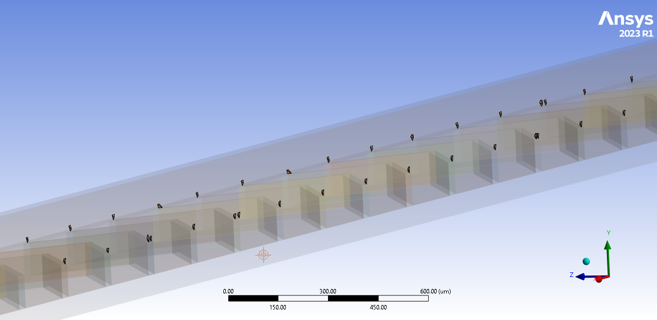
SubscriberOh ok, I think I finally understand what you meant to say. Yeah, that would create several fluid domains or bodies. I will give it a go. Thank you so much. Additionally, due to the angle of the flow promoters or vortex generators, the leading tip edge is almost in line or even further in than the tail of the preceding promoter. Again, thank you so much for all your help
-
February 9, 2024 at 9:30 pm
adave12
SubscriberHi ,
I did use the method that you told me about . However , there has been a loss in the quality of the mesh and the non-convergence of quantities is posing issue.
-
February 9, 2024 at 11:16 pm
mjmiddle
Ansys EmployeePlease show soem pictures of the lower quality mesh regions. You can vew with section plane if it helps to look internally. Convergence problems can be due to many things and the mesh quality may not be the reason. Where are you analyzing (Fluent, CFX)? You earlier said it was for CFD analysis.
-
February 10, 2024 at 12:10 am
-
February 10, 2024 at 12:19 am
mjmiddle
Ansys EmployeeCan you zoom in to one of these regions to actually see the elements? Whta direction is the sweep? Top to bottom?
Cna you show a section pane through one of these regions showing all mesh?
-
- The topic ‘Multizone meshing issue’ is closed to new replies.


-
4708
-
1565
-
1386
-
1242
-
1021

© 2026 Copyright ANSYS, Inc. All rights reserved.


