-
-
June 4, 2024 at 3:15 pm
Livio Michele Moesch
SubscriberDear Members,
I am currently having a problem with a multiphase VOF simulation of a rotating capillary tube designed in 2D with axisymmetric swirl. The geometry looks as follows

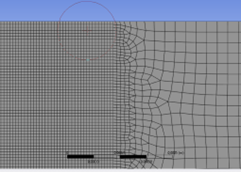
with gravity in -x direction, the tube being filled with water on the bottom part, and air on top. My mesh is finer in the central part as this is where the interesting breakups should take place (checking my mesh results in a good minimum orthogonal quality [0.51] and maximum aspect ratios [5], all cell areas are positive and the overall look is good too in my opinion). The time formulation is transient, the viscous model laminar, and the rotational speed of the walls set to 1 rad/s.
My final goal is to impose variable wallspeeds to achieve some sort of convective breakup and visualize different mode-shapes previously explored by mathematical models. Right now my model does not lead to any type of senseful solution though, as even with constant rotational wall-speeds the solution seems to be heavily dependent on the chosen timestep size.
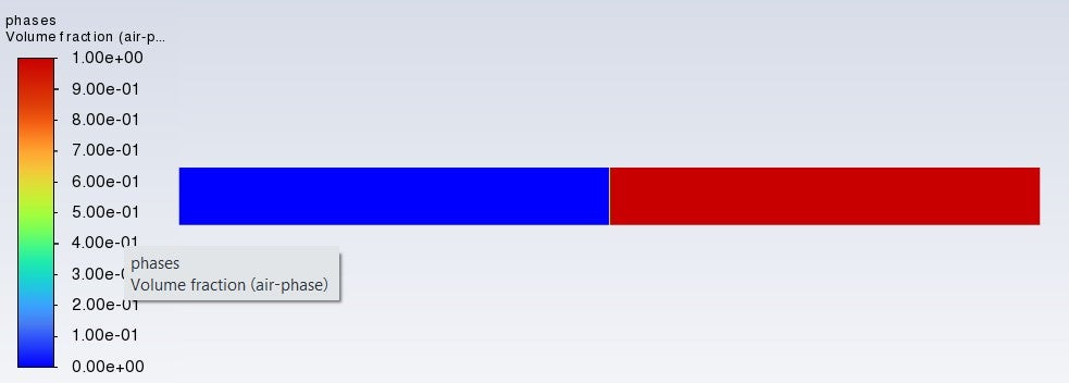
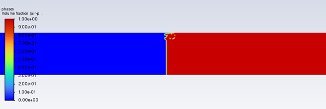
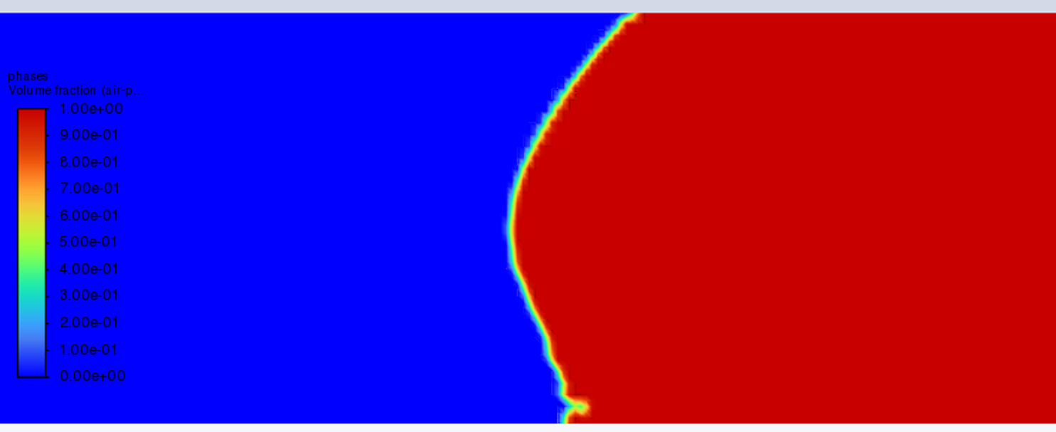
Choosing a timestep of 5e-5s leads to the fluid detaching from the wall and the solution is diverging.
Decreasing the timestep to 2e-5 makes the solution diverge later and brings me closer to what I'd like to see
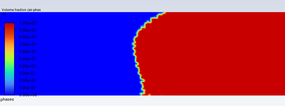
Decreasing it even further to 1e-5s is where the big problem starts to arise; there is no detachment from the wall anymore, and the fluid surface behaves perfectly smooth exactly as if there was no wall movement at all (hence just the water flowing down the stationary capillary tube). Both Screenshots are taken after the identical flowtime.
I tried working with the VOF Stabilization Methods which were introduced in the last years, as in some cases the swirl velocities of the mixture went very high which is not physical and this may lead to a numerical instability (and expected to be smoothed out as described in the User's Guide) 26.8.1. General Solution Strategies (ansys.com)
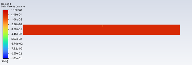
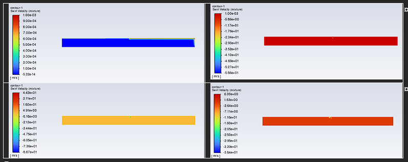
Swirl velocities when spinning at 1rad/s, 5e-5s, when divergence happens
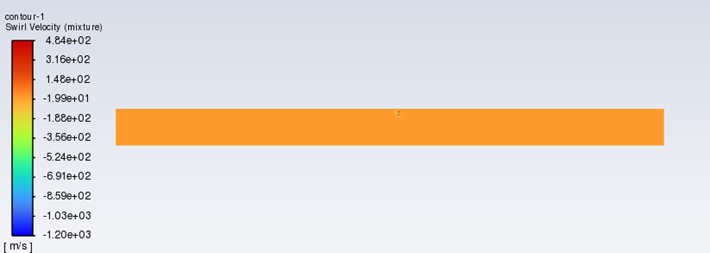
Swirl velocities when spinning at 1rad/s, 3e-5s, when divergence happens, with stabilization methods activated
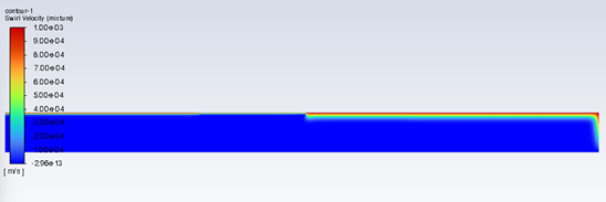
How my swirl velocities look when there's no divergence, and how I would expect them:
Unfortunately, even after activating settings optimization and advanced stabilization, and limiting the maximum swirl velocity to 50m/s, rotating my wall at a constant speed of 1rad/s I still get vastly different results depending on the chosen timestep.
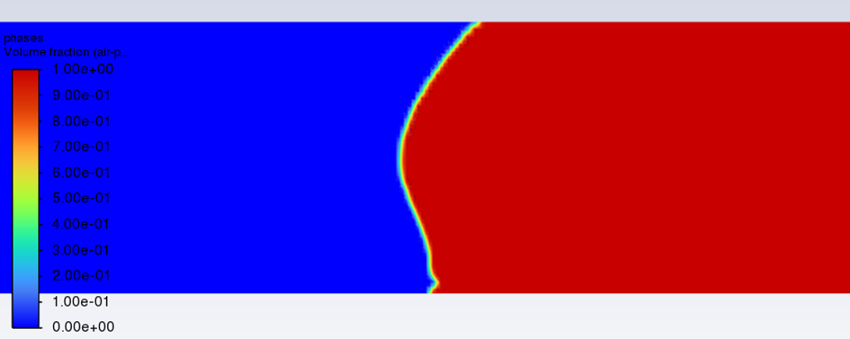
Starting with 3e-5s:
Diverging, with swirl speeds going all over the place
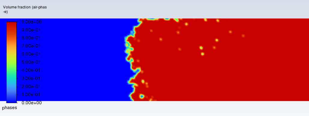
With 2e-5s:
A similar behaviour to before with the same timestep, but kind of smoothed out. Unfortunately the solution still diverges shortly after this flowtime.
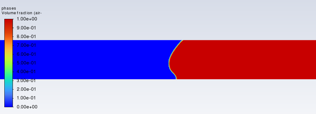
And decreasing it further to 1e-5s:
No divergence anymore, but again a behaviour that seems like it does not care about the moving wall at all (I performed simulations with stationary walls and it looks identical)
I am posting this as I feel like I am running out of options after having tried tried checking many tutorials and handbooks. I'd be very happy about suggestions as to why the wall detachment and solution close to the center point which is interesting to me differ so vastly, when changing only the timestep size. The results of bigger timestep sizes seem more physical to me and can't be replicated by using the same amount of flowtime through smaller ones, which tends me to believe that this is a numerical issue.
-
June 5, 2024 at 12:22 pm
Rob
Forum ModeratorThat should behave OK. Can you re-try in 24R1?
-
July 8, 2024 at 3:59 pm
Livio Michele Moesch
SubscriberI am replying late as the forum was down for maintenance a long time. I downloaded 24R1 and tried running the same case, but that didn't lead to substantial changes. The timestep sizes that were diverging before are still diverging, even if a little later with actually slightly different contours, the stable ones from before lead to basically identical results.
Timestep 3e-5s, Velocity limited to 50m/s, Wall rotating at 1 rad/s
Timestep 1e-5s, Velocity limited to 50m/s, Wall rotating at 1 rad/s
As the densities of the two phases are very different and hence the problem that arose was excactly what Fluent describes as critical for stability, I tried pushing the velocity limiting even further (to 1m/s, with 3e-5s as timestep), as 1rad/s with a radius of 1mm means speeds in the orders of magnitude around 0.01m/s. Unfortunately this lead to unphysical results, something known in the Fluent Guides. It's also worth noting that I cannot replicate this unphysical contour (which is present throughout the whole calculation) using smaller timesteps (they would again lead to a fully "flat surface", looking exactly as if there was no rotation imposed at all).
Increasing the rotational speeds to 50rad/s constant or applying a 50rad/s triangular peak don't change the profile when simulating with the timestep size 1e-5s, and with bigger timesteps I get the same divergence as before. The backflow in on the open boundary changes a little, indicating to me that Fluent is not disregarding the change in rotational speed; but as to what I expect from the solution and want to prove I am not able to get the software to perform results that should be phyiscal in my opinion.
Timestep 1e-5s, Velocity limited to 50m/s, Wall rotating at 50 rad/s
I'd be glad about final thoughts on where these problems could arise from and what I could be doing wrong.
-
-
July 10, 2024 at 9:22 am
Rob
Forum ModeratorHow are you getting the air phase being drawn back into the domain at the end? Check the boundary settings for reverse flow.
Thinking about it more. Are you moving the wall, or the fluid zone?
-
July 10, 2024 at 3:52 pm
Livio Michele Moesch
SubscriberThere is reverse flow, which I read is quite common for capillary VOF applications. I specified the phase for the backflow as air in this case, as this is something I would expect in an experimental setup (and as it had to be specified one way or the other). It is worth noting though that I set up simulations at different rotational speeds, keeping everything equal and specifying the backflow phase as water, to make sure that this wasn't the problem.
I am moving the wall, it is rotating around the X-Axis.
-
-
July 11, 2024 at 8:20 am
Rob
Forum ModeratorReverse flow is common, I agree, but check which phase is reversing. Try rotating the fluid zone & wall at zero relative. Should give much the same effect but may resolve some of the issues. The other comment from a colleague was to drop the time step alot further: there can be a situation where too high a step is stable because everything is smoothed out.
-
August 26, 2024 at 9:10 am
Livio Michele Moesch
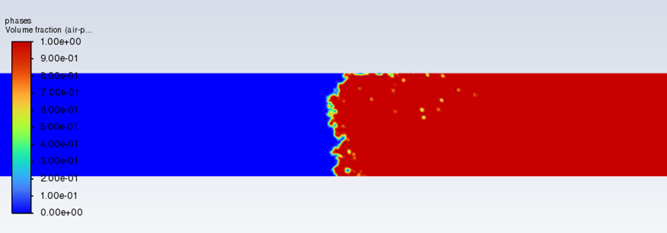
SubscriberThe only two existing phases are water (blue) and air (red), as I had to chose one and regarded it as more physically senseful I set air as the backflow phase and hence it is also the one that is reversing.
I tried lowering the time step by another order of magnitude to 1e-6s, which lies an order of magnitude below the minimum time step when running the simulation with adaptive time stepping at a Global Courant number of 0.9, and after careful post-processing I still don’t see any effect of the wall rotation on the fluid interface.
I have been trying to understand your advise of “rotating the fluid zone & wall at zero relative”; do you mean following a (single) moving reference frame approach? My current understanding of this is that the momentum equations would be solved in terms of a relative velocity U_{rel} which can be transformed back into a U in a stationary reference frame. By having that moving reference frame additional terms appear in the momentum equation in this case being the Centripetal and Coriolis force and a (d\omega) / (dt) * r term.
- The solution obtained with this approach should differ from the solution obtained by moving the wall by no more than numerical inaccuracies though, right?
DrAmine wrote here Should fluid be rotating or wall be rotating (ansys.com) that the two solutions will only lead to similar results if the centripetal and coriolis forces are low. This confuses me, as it seemingly goes against the reasoning recommended by you and my understanding. Adding the new terms to the momentum equation by solving from a relative frame of reference should be at least physically be the same as solving from a stationary frame of reference and implementing the wall rotation through the boundary conditions, right?
I would be very grateful about a quick clarification on whether this throught process is correct and why DrAmine gave this answer to a similar problem. Thank you very much already for your contribution.
-
-
August 27, 2024 at 1:58 pm
Rob
Forum ModeratorMoving the wall & moving the fluid (so also moving the wall) should give the same result. What is the tube radius? What happens if you repeat the model with a 30 degree sector and rotational periodic boundaries?
-
- The topic ‘Multiphase VOF simulation of a rotating capillary tube’ is closed to new replies.


-
4678
-
1565
-
1386
-
1242
-
1021

© 2025 Copyright ANSYS, Inc. All rights reserved.


