-
-
October 13, 2023 at 8:50 am
umesh_maheshwari
SubscriberHello All
I have a query related to boundary conditions for my vibration simulation test carried out on multilayer PCB.
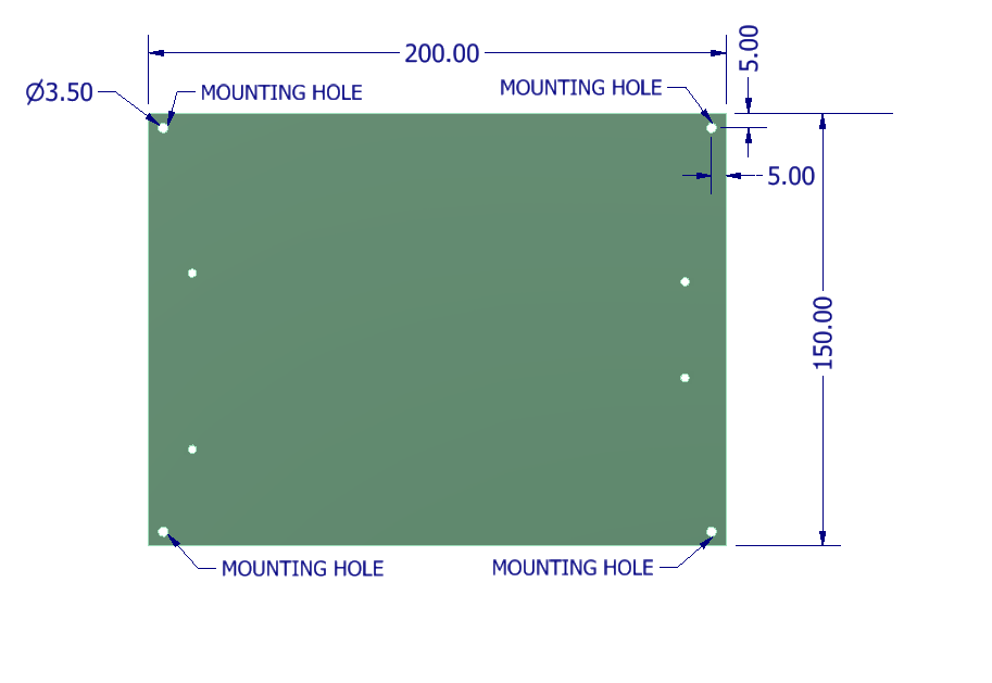
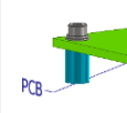
I have fixed the PCB on vibration fixture using 4 Nos. of M3 screws+ Plain washer+ Spring Washer using aluminum spacer (ID:3.5 mm , OD: 7mm & Length 10mm) between PCB bottom and vibration fixture top and a torque of 58N-cm is applied on the screws. (refer attached figure)
In actual vibration test first mode natural frequency observed is 136Hz.
When i am simulating the same in Ansys workbench my first mode natural frequency is 156 Hz.
Equivalent mechanical properties of PCB are:
E =28.45 GPa & Poisson's ratio : 0.13 density : 2420 kg/m^3
PCB dimensions are : 200 x 150 x 2.404 mm
Base PCB mass : 175 gm
For my simulation , i have assumed isotropic material for PCB with above properties and hole edges (neglecting the aluminium spacers) are taken as fixed boundary condtion in place of washer area , frequency obtained is 152 Hz.I tried with PCB trace mapping technique also. In that case , I used Ansys FR4 & copper properties for the PCB and again fixed boundary condition is taken as hole edges , again natrual frequency observed is
I have not done pre-stress modal analysis and no damping assumed.
I think there is something wrong in my boundary condition that the reason my simulation results are not matching with actual vibration test.
Should i consider aluminium spacer also in simulation?
please let me know where i am doing wrong.
Thanks in advance. -
October 13, 2023 at 9:37 am
ErKo
Ansys EmployeeI think perhaps include some more masses (3 x sensors, and mass of largest electronic components, or circuits) that is missing as this will lower the FE natural freq. By including damping, can also lower the frequencies in FE.
All the best
Erik
-
October 13, 2023 at 12:16 pm
umesh_maheshwari
Subscriber@ Erik
Sir
- The mass of sensors (acceleraometers) used is less than 1 gm, whether this will affect ?
- There are no components mounted on the PCB , vibration is done for the bare PCB. In the picture attached whatever visible is copper trace on PCB , according to copper content equivalent properties are calculated and used here.
- I can include damping but what will be the value of it , as during actual vibration test Q observed for a typical sensor is as below.
I used trace mapping , to get the copper percentage in each layer and then calculated the equivalent properties of PCB using Ansys FR4 & Copper mechanical properties.
Can you explain what why i should model assembly shown in above figure and what will be boundary condition?
Thanks in advance.
-
October 13, 2023 at 12:51 pm
ErKo
Ansys EmployeeHi
I would still include all masses that are there – also compare your FE model mass to the real model mass.
Also how well do you know the material properties (you certain of all the properties – often there is a variation) – sometimes we need to alter/change them a bit to get better agreement with test data.
Finally damping is a user input so the user needs to know it or measure it (see the help manual for different forms of damping that can be used in modal with Ansys).
As for prestress, unless you really needed to compress it a lot in order to fit into the fixture, then I think this is very minor.
All the best of luck and perhaps some members have some more feedback. -
October 16, 2023 at 9:35 am
umesh_maheshwari
SubscriberI have compared the masses :
Base PCB mass : 175 gm
FE Model PCB Mass :175.23 gm
I have modelled the aluminium spacer & PCB and connection is made using beam element (represeting M3 screw) which is made by connecting PCB top edge and Specer Bottom edge and pre-load of 1140N is applied and frictional contact between PCB bottom face and spacer top face is considered.
For No pre-stressed condition , first mode natural frequency : 152.4 Hz
For pre-stressed condition , first mode natural frequency : 148 Hz
I think issue with boundary condition which i am using.
————————————————————————————————————————————————————————–
-
October 30, 2023 at 8:17 am
umesh_maheshwari
Subscriber@ Erik
" Also how well do you know the material properties (you certain of all the properties – often there is a variation) – sometimes we need to alter/change them a bit to get better agreement with test data."
Sir
Your question is valid , I am using FR4 properties given in Ansys Mechanical while this PCB board is made from Isola 370HR (FR4) dielectric material. For this i don't have all the 9 properties values required for an orthotropic material.
From datasheet of Isola 370HR , i got few properties which are as below:
E1 (along length direction) : 3744 ksi ( ~ 25814 MPa)
E2 (along cross direction ) : 3178 ksi (~ 21912 MPa)
https://www.isola-group.com/wp-content/uploads/sites/2/data-sheets/370hr.pdf
Poisson's Ratio :
A. Length direction : 0.177
B. Cross direction : 0.171The other properties details are missing like E3 , Vz , G12 , G13 & G23.
Since , these properties are not available , i have rely on FR4 properties given in Ansys Mechanical. Here, also i observed that for shear modulus calculation formula used is valid for isotropic material.
like Ex : 20.4 GPa
vxy : 0.11
if you see the Gxy value it is 9200 MPa which will come from G = E/ (2*(1+v)).
I don't have exact material properties , that may be one of the reason that modal frequency is not matching.
Please suggest if you came across this material or having mechanical properties.
-
- The topic ‘Multilayer PCB modal analysis first mode natural frequency related.’ is closed to new replies.


-
5004
-
1681
-
1387
-
1248
-
1021

© 2026 Copyright ANSYS, Inc. All rights reserved.


