-
-
August 6, 2025 at 2:36 pm
Sara.Ranjbareslamloo
SubscriberHi everyone,
Using the command below, I was able to simulate a laser (single track moving). Now I want to extend this to multiple layers. Can anyone help me figure out how to dynamically change the Z position?g=0.3 !absorbityp=230 !Laser Power in wattsw=50e-6 !radius of moving sourceA=(2*g*p)/(22/7*w**2)B=-3C=0D=1200/1000 !scan speedE=0F=w**2*DIM,HEAT_FLX1,TABLE,8,14,1,,,,0!! Begin of equation: A*exp(B*(({X}-C)^2+({Y}-D*{TIME}-E)^2)/F)*SET,HEAT_FLX1(0,0,1), 0.0, -999*SET,HEAT_FLX1(2,0,1), 0.0*SET,HEAT_FLX1(3,0,1), A*SET,HEAT_FLX1(4,0,1), B*SET,HEAT_FLX1(5,0,1), C*SET,HEAT_FLX1(6,0,1), D*SET,HEAT_FLX1(7,0,1), E*SET,HEAT_FLX1(8,0,1), F*SET,HEAT_FLX1(0,1,1), 1.0, -1, 0, 1, 2, 2, 19*SET,HEAT_FLX1(0,2,1), 0.0, -2, 0, 2, 0, 0, -1*SET,HEAT_FLX1(0,3,1), 0, -3, 0, 1, -1, 17, -2*SET,HEAT_FLX1(0,4,1), 0.0, -1, 0, 1, 20, 3, 1*SET,HEAT_FLX1(0,5,1), 0.0, -2, 0, 1, 3, 2, -1*SET,HEAT_FLX1(0,6,1), 0.0, -1, 0, 1, -2, 2, 21*SET,HEAT_FLX1(0,7,1), 0.0, -2, 0, 2, 0, 0, -1*SET,HEAT_FLX1(0,8,1), 0.0, -4, 0, 1, -1, 17, -2*SET,HEAT_FLX1(0,9,1), 0.0, -1, 0, 1, -3, 1, -4*SET,HEAT_FLX1(0,10,1), 0.0, -2, 0, 1, 18, 3, -1*SET,HEAT_FLX1(0,11,1), 0.0, -1, 0, 1, -2, 4, 22*SET,HEAT_FLX1(0,12,1), 0.0, -1, 7, 1, -1, 0, 0*SET,HEAT_FLX1(0,13,1), 0.0, -2, 0, 1, 17, 3, -1*SET,HEAT_FLX1(0,14,1), 0.0, 99, 0, 1, -2, 0, 0! End of equation: A*exp(B*(({X}-C)^2+({Y}-D*{TIME}-E)^2)/F)!-->sf,s1,hflux,%HEAT_FLX1% -
August 14, 2025 at 2:42 pm
Chandra Sekaran
Ansys EmployeeThis function was built in MAPDL function builder GUI and then these commands were taken out of the log file in MAPDL. The function builder in MAPDL support multi-regime functions. For example you could have different equations for different Z value ranges. Perhaps that is what you need. Or if your equation can be modified to add in a Z parameter that can also be done.
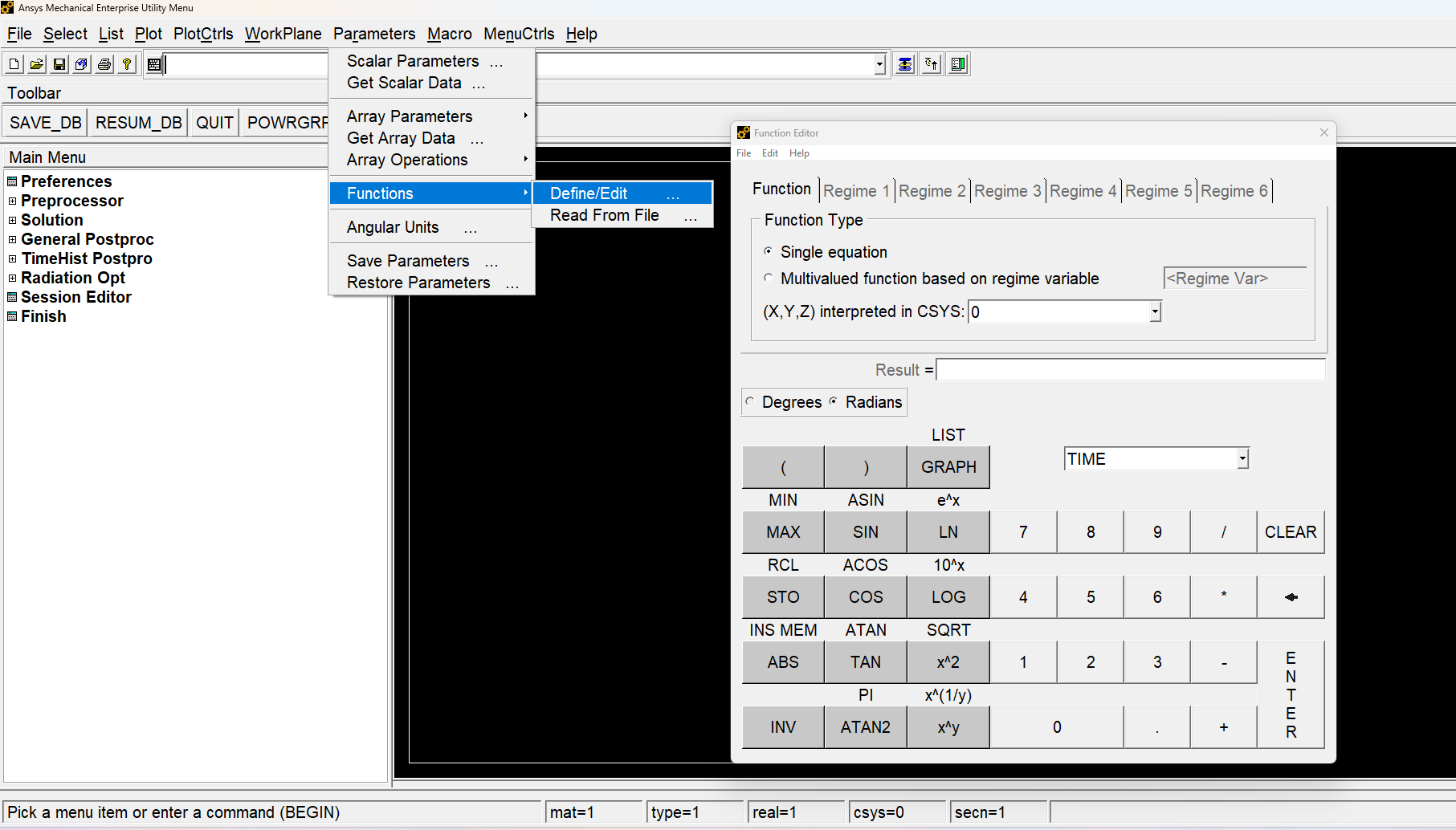
Here are steps involved.
1. Go to function editor in MAPDL and create the equation. For example “0.01*X*TIME^2” . Save the function to a file.
2. In MAPDL import the saved function as a table parameter using GUI. It will ask for the name of the function. Let us say I call it “PRES”
3. Then you use %PRES% like you would with any other table array in SFE,SFA, BF etc commands.
For use in Mechanical, do all the way to step 2 above in MAPDL. Then look at the log file and copy the function definition (shown below in yellow highlight). Manually add the SF command to apply the load.
*DEL,_FNCNAME
*DEL,_FNCMTID
*DEL,_FNCCSYS
*SET,_FNCNAME,'pres1'
*SET,_FNCCSYS,0
! /INPUT,eqn1.func,,,1
*DIM,%_FNCNAME%,TABLE,6,9,1,,,,%_FNCCSYS%
!
! Begin of equation: 0.1*sqrt({X}^2+{Y}^2)
*SET,%_FNCNAME%(0,0,1), 0.0, -999
*SET,%_FNCNAME%(2,0,1), 0.0
*SET,%_FNCNAME%(3,0,1), 0.0
*SET,%_FNCNAME%(4,0,1), 0.0
*SET,%_FNCNAME%(5,0,1), 0.0
*SET,%_FNCNAME%(6,0,1), 0.0
*SET,%_FNCNAME%(0,1,1), 1.0, -1, 0, 2, 0, 0, 2
*SET,%_FNCNAME%(0,2,1), 0.0, -2, 0, 1, 2, 17, -1
*SET,%_FNCNAME%(0,3,1), 0, -1, 0, 2, 0, 0, 3
*SET,%_FNCNAME%(0,4,1), 0.0, -3, 0, 1, 3, 17, -1
*SET,%_FNCNAME%(0,5,1), 0.0, -1, 0, 1, -2, 1, -3
*SET,%_FNCNAME%(0,6,1), 0.0, -1, 16, 1, -1, 0, 0
*SET,%_FNCNAME%(0,7,1), 0.0, -2, 0, 0.1, 0, 0, -1
*SET,%_FNCNAME%(0,8,1), 0.0, -3, 0, 1, -2, 3, -1
*SET,%_FNCNAME%(0,9,1), 0.0, 99, 0, 1, -3, 0, 0
! End of equation: 0.1*sqrt({X}^2+{Y}^2)
!-->
cmsel,s,surface1
sf,all,pres,%pres1%
-
August 27, 2025 at 8:23 pm
Sara.Ranjbareslamloo
SubscriberI already did the procedure you mentioned to get the command, but it's just for one laser track and I am not able to extend it in vertical and horizental direction. my final goal is simulate like this toturial Additive Manufacturing AM, Laser Metal Deposition LMD horizontal advanced model 2D Gauss heat source - YouTube.
-
- You must be logged in to reply to this topic.


- The legend values are not changing.
- LPBF Simulation of dissimilar materials in ANSYS mechanical (Thermal Transient)
- Convergence error in modal analysis
- How to model a bimodular material in Mechanical
- APDL, memory, solid
- Meaning of the error
- Simulate a fan on the end of shaft
- Nonlinear load cases combinations
- Real Life Example of a non-symmetric eigenvalue problem
- How can the results of Pressures and Motions for all elements be obtained?

-
3912
-
1414
-
1256
-
1118
-
1015

© 2025 Copyright ANSYS, Inc. All rights reserved.


