We have an exciting announcement about badges coming in May 2025. Until then, we will temporarily stop issuing new badges for course completions and certifications. However, all completions will be recorded and fulfilled after May 2025.
General Mechanical

General Mechanical

Topics related to Mechanical Enterprise, Motion, Additive Print and more.

MPC184 and LINK180 connection for thermal expansion

    • Matt92x
      Subscriber

      Hello everyone,


      I'm working on a complex project for my thesis using Ansys APDL involving cables and revolute joints.


      Since all my solutions didn't work well, I tried to simplify the problem to find where I was wrong. 


      This simplified model consists in a bar (modeled with LINK180) connected at its ends through pins on two wedged beams (modeled with BEAM188). This bar has tension only behaviour (reason why i choose LINK180 instead of another beam element) and can rotate on the beam's axes. I need to find the displacement and stress on the stucture caused by an elongation on the bar (which I apply using a thermal expansion)


      Firstly I tried to connect directly link element with beams; applying a difference of Temperature DT, the bar expands and consequently beams bends on the external side. This is actually what I want but, since link180 nodes haven't rotational dof, if one beam moves upward/downwards this solution doesn't work anymore.


      So I defined an MPC184 Revo Joint element on both side of the bar to conect it on the beams. In this case if I apply the same DT nothing happened, as if the relative displacement dof was constrained.


      Probably I'm wrong but it seems that the issue is related to the command NLGEOM,ON which is needed to use MPC elements.


      Here below I attach code files of both cases.


      Could you help me to find a solution and understand where am I doing wrong, please?


      Thank you in advance.


      Best regards.


    • Wenlong
      Ansys Employee

      Hi,


      Ansys staff cannot download attachments from the student community. Are you trying to simulate a case like this:


      May I ask why directly merging the nodes at the end of the link and beam doesn't work (regarding the following quote)? I am imagining if the beam tip moves upward or downward, the link can move with it.


      if one beam moves upward/downwards this solution doesn't work anymore. 


      For the MPC approach, I found this sentence on the manual, maybe it will be helpful? (Ref: https://ansyshelp.ansys.com/account/secured?returnurl=/Views/Secured/corp/v201/en/ans_elem/Hlp_E_MPC184link.html)


      The MPC184 rigid link/beam element with KEYOPT(2) = 1 can also be used in applications that call for thermal expansion on an otherwise rigid structure. The direct elimination method cannot be used for thermal expansion problems


      Regards,


      Wenlong


      Useful Links


      /

    • Matt92x
      Subscriber

      Hi Wenlong,


      Thank you very much for your quick reply.


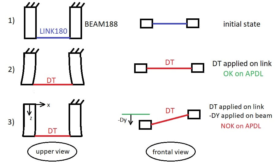
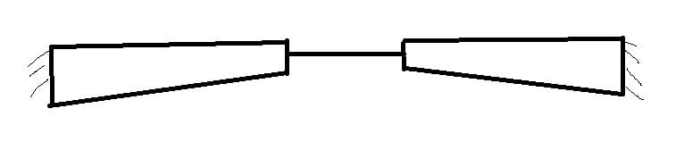
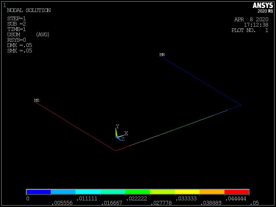
      Yes, the structure is more or less the one you depicted. I try to describe it better with the image below, in which I drew:

               1) Initial configuration


               2) Solution applying only DT on link element - works on APDL using direct merging as you suggest, showing elongation of the link and bending on beams


               3) Solution applying DT on link and a DY displacement on a beam element


      In this last case APDL doesn't work, when I try to solve nothing happens and message "solution is done" is not showed by the program.
      Please correct me if I am wrong, but could be related to the fact that link do not have rotational degrees of freedom?


      However I write my code using direct merging at the end of this post so you can see if I made any mistakes.


      Instead, using MPC184 revolute joint, if a DY is applied on beam element I'm able to find the solution. But when I introduce thermal expansion (with KEYOPT(2)=1 ), the program seems consiering it only for link element, showing the stress as if the joints constrain also the deformations in the axial direction.


      Thank you again, I look forward to receiving any feedback on your side.


      Best regards,


      Matteo


      APDL Code below:


      /CLEAR, START, NEW


      *set,length,0.5


      *set,thick,0.08


      *set,radius,0.036


      *set,width,0.1


      /prep7


      ET,1,LINK180


      mp,ex,1,366    


      mp,prxy,1,0.33         ! Unkonwn


      mp,alpx,1,0.000120     ! [1/°C] 


      TREF,30


      SECTYPE,1,LINK,CSOLID


      SECDATA,0.0041         ! area -> r = 3.6 cm ca. 


      SECCONTROL,,1          ! TENSION ONLY


      ET,2,BEAM188


      mp,ex,2,10e8


      mp,prxy,2,0.33


      SECTYPE,2,BEAM,csolid,Section


      SECDATA,0.036


      K,2,0,0,-width


      K,3,0,0,0


      K,4,length,0,0


      K,6,length,0,-width


      L,2,3   ! 1 First Beam


      L,3,4   ! 2 Thermal link


      L,4,6   ! 3 Second Beam


      TYPE,1 


      MAT,1 


      SECNUM,1


      LSEL,s,LINE,,2


      LESIZE,all,,,10


      LMESH,2


      ALLSEL,all


      TYPE,2


      MAT,2


      SECNUM,2


      LSEL,s,LINE,,1,3,2


      LESIZE,all,,,4


      LMESH,all


      ALLSEL,all


      !


      !


      ! ---   SOLUTION   --- !


      !


      !


      /SOLU


      antype,static,new


      ! Constraint on base nodes


      nsel,s,NODE,,16


      D,all,all,0


      allsel,all


      D,12,ux,0


      D,12,uy,-0.05


      D,12,uz,0


      D,12,rotx,0


      D,12,roty,0


      D,12,rotz,0


      ! Apply DT on bar nodes


      nsel,s,,,1,11,1


      BF,all,TEMP,50


      ALLSEL,all


      outres,all,all


      solve


    • Wenlong
      Ansys Employee

      Hi Matteo,


      Thank you very much for your detailed explanation and the command attached. It is a learning process for me too. 


      I rerun your input file, and I think it works fine (the common node approach). I think the issue you are seeing is related to the APDL plotting capability. If I use "/eshape, 0" to turn off the sectional play, the deformation looks fine. 


      But if I turn on the sectional display, it becomes the same as you mentioned. 


      I've also tried a single beam model and do the sectional plot, again it shows no contour plot. I will continue investigating the reason and get back to you once I find an answer. 


      Regards,


      Wenlong


    • Matt92x
      Subscriber

      Hi Wenlong,


      Thank you again for your contribution. Deeply appreciated!


      Unlike you I'm not able to solve the structure with the code I attached in the previus post. In particular:


      1) When I try to solve using only Dy displacement, the program gives me result identical to yours (hence probably is not considering DT?)


      2) When I add also DT for the link elements, program doesn't give me a solution, and the following error comes out on the Output Window:


       *** ERROR ***                           CP =       2.578   TIME= 152:05


       A large negative pivot value ( -1.110223025E-16 ) has been encountered


       in the global assembled matrix at the UY degree of freedom of node 7.


       This may be caused by a bad temperature-dependent material property


       used in the model.


       *** ERROR ***                           CP =       2.578   TIME= 152:05


       There are 2 small equation solver pivot terms (e.g., at the UY degree


       of freedom of node 8).  Please check for an insufficiently constrained


       model.


      Actually I'm using an APDL version older than yours (mine is 18.2). Do you think something has changed between the two version and that I should therefore update the program?


      Best regards,


      Matteo


    • Wenlong
      Ansys Employee

      Hi Matteo,


      I forgot to mention that I modified your input a little bit to make sure the nodes are constrained well. in my model I also applied DT. Please find it below. I don't think it is due to version change since these are very conventional functions. 


      Regards,


      Wenlong


      /CLEAR, START, NEW


      *set,length,0.5


      *set,thick,0.08


      *set,radius,0.036


      *set,width,0.5


      /prep7


      ET,1,LINK180


      mp,ex,1,366    


      mp,prxy,1,0.33         ! Unkonwn


      mp,alpx,1,0.000120     ! [1/°C] 


      TREF,30


      SECTYPE,1,LINK,CSOLID


      SECDATA,0.0041         ! area -> r = 3.6 cm ca. 


      SECCONTROL,,1          ! TENSION ONLY


      ET,2,BEAM188


      mp,ex,2,10e8


      mp,prxy,2,0.33


      SECTYPE,2,BEAM,rect


      SECDATA,0.05,0.08


      K,2,0,0,-width


      K,3,0,0,0


      K,4,length,0,0


      K,6,length,0,-width


      L,2,3   ! 1 First Beam


      L,3,4   ! 2 Thermal link


      L,4,6   ! 3 Second Beam


      TYPE,1 


      MAT,1


      SECNUM,1


      LSEL,s,LINE,,2


      LESIZE,all,,,10


      LMESH,all


      ALLSEL,all


      TYPE,2


      MAT,2


      SECNUM,2


      LSEL,s,LINE,,1,3,2


      LESIZE,all,,,4


      LMESH,all


      ALLSEL,all


      !


      !


      ! ---   SOLUTION   --- !


      !


      !


      NLGEOM, ON


      /SOLU


      antype,static,new


      ! Constraint on base nodes


      nsel,s,LOC,Z,-width


      nsel,R,LOC,X,length


      D,all,all,0


      nsel,s,LOC,Z,-width


      nsel,R,LOC,X,0


      D,all,ux,0


      D,all,uy,-0.05


      D,all,uz,0


      D,all,Rotx,0


      D,all,Roty,0


      D,all,Rotz,0


      esel, s, etype, 1


      bf,all,temp,50


      outres,all,all


      SOLVE


      !


      !


      ! ---     POST1    --- !


      !


      !


      /POST1


      allsel,all


      /view, 1, -0.5, 0.395, 0.77


      /eshape,1


      plnsol,u,SUM


    • Matt92x
      Subscriber

      Hello Wenlong,


      I'm still not sure that the program is taking into account the BF command. If I try to run your original code and then the same but without BF command, final results are the same (i.e. only Dy effect is applied on the structure and veasible with the command plnsol,u,sum).
      Could you please confirm that you find the same solution too?


      There must be something wrong in the definition of LINK180 when an element is oriented with an inclined position (because DT works if nodes are oriented along x,y or z axes).


      Probably I need to find another way to simulate the elongation of the bar if I want also its rotation. I was thinking about using a spring element, but I'm not sure it could work only in tension. Do you maybe know if there are other possibilities?


      Thank you as usual for your help.


      Regards,


      Matteo 

    • Wenlong
      Ansys Employee

      Hi Matteo,


      Sorry for the late reply. My mistake that I didn't notice the result before and after applying DT is the same. You raised up a good point that the orientation of the link element may play a role here. I was occupied and couldn't find time on this but I will continue investigating and let you know if I have anything. 


      Regards,


      Wenlong


    • Wenlong
      Ansys Employee

      Hi Matteo,


      I tried the model in Ansys Mechanical since and I am able to get it run. The model is set up with the beam & Link element connected. I applied similar boundary conditions (first step displacement and second step temperature) and I am able to get thermal strain. I would recommend you try it in Mechanical. You can also generate an APDL input file from Mechanical (It can be done right click on the solution - -> Open solver directory, then you will find a ds.dat file which is the input. Apologies if you already know this.)


      (The website seems to have some issue and I cannot insert an image)


      LINK180 element also offers the tension-only option and you can define that using SECCONTROL command (Ref:https://ansyshelp.ansys.com/account/Secured?returnurl=/Views/Secured/corp/v194/ans_cmd/Hlp_C_SECCONTROL.html)


      Regards,


      Wenlong


      ================ Note ====================


      If you have trouble opening the links I attached, please see the first useful link below


      Useful Links


    • Matt92x
      Subscriber

      Hello Wenlong,


      I'm not sure I understand clearly what you mean. Your suggestion is to solve the structure using Workbench instead of APDL, and then create a ds.dat containing this solution which could be open in APDL, right?


      If yes, it would be very helpful since I need the solution in APDL domain.


      However, I'm not very familiar with using Workbench (I worked with it only a couple of time). For sure I can manage this simplified model quite easily, but probably not the more complex one. So my idea is to proceed with the following steps:


      1) Create model and constraints with APDL and save it in a readable format for Workbench
      2) Solve this model in Workbench
      3) Export the solution in APDL and display it with /post1 environment


      Do you think is it possible to do everything?


      Thank you for your precious support of these days.


      Regards,


      Matteo

    • Wenlong
      Ansys Employee

      Hi Matteo,


      Yes. Workbench Mechanical can create a ds.dat file that can be read into APDL. After imported to APDL, I would use a "cdwrite,all, myinput,inp" to generate an input file that's more suitable for APDL (The ds.dat file has many commands for Mechanical). Note that this new myinput.inp generated does not have the "/solu" and "/post1" commands, so you will need to modify that. (It does have the boundary conditions defined though.)


      After modification, I run my_input.inp file in APDL and I am able to get the same result as the Mechanical. Please see below:


      If you want to input the APDL into Workbench, you can use an "external model" and add your input file. Then you can connect the external model to the "model" of a Static Structural Analysis. You will need to add the boundary conditions though. 


      There are probably better ways to achieve this and others can comment on that. 


      Regards,


      Wenlong


    • Matt92x
      Subscriber

      Hello Wenlong,


      I tried your suggestion but I'm still having the same issue also in Workbench.
      Here below all the steps I made:


      1) As you suggested, I used the APDL "external model" as input file. Hence I connected it to the Static Structural model.
      However, since in Workbench LINK180 is not defined, I had to modify first the APDL code assigning "temporarily" a BEAM188 element instead of link. 


      2) Afterward, I modified Engineering data for the thermal bar (defining new Ex, Prxy and Alpx) and I inserted an APDL Command code in Line Body 1 in order to make it recognized as a link (and with SECCONTROL,,1 tension only input).


      3) Finally I added fixed contraints and thermal input on the nodes as usual. I also activate non-linear analysis option.


      Unfortunately, when I try to update the solution, the following warning/error appear and they seems similar to the APDL ones:


      Probably there are some steps I missed or I did something wrong. Please, could you tell me if you found these issues too?


      I attach my wbpz file if you want (and if you have some time of course) to compare it with yours.


      Thank you very much.


      Regards,


      Matteo

    • Wenlong
      Ansys Employee

      Hi Matteo,


      Sorry Ansys staff cannot download attachments from the student community. Next time you can add an image of your model set up by taking a screenshot.


      This message means your model is not fully constrained. I am guessing you are only applying fixed support (which only fixes the translational DOFs). If so, try to add a "fix rotation" boundary to the support and it should solve the problem. 


      Regards,


      Wenlong


    • Wenlong
      Ansys Employee

      Hi Matteo,


      I forgot to mention that, in Mechanical, if you want to view the beam section results, you need to turn the "Beam section results" in "Solution" details to "yes". If the solution is already done, then you want to clear the generated data (by right click on "Solution" --> Clear generated data) and rerun the model.


      Regards,


      Wenlong


    • Wenlong
      Ansys Employee

      Hi Matteo,


      I forgot to mention another thing: you can change the element type to link in Mechanical without using a command. 


      Regards,


      Wenlong


Viewing 14 reply threads
  • The topic ‘MPC184 and LINK180 connection for thermal expansion’ is closed to new replies.