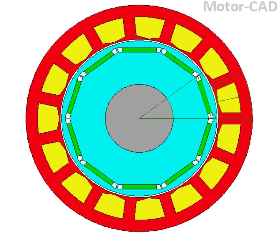
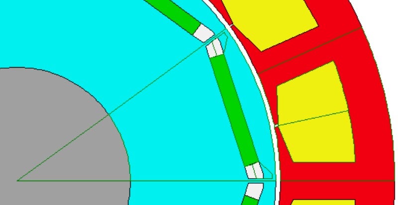
Hello everyone! I have 5 pp, 15 slots, conc. windings IPM motor, and I'm having issues at matching the results of Motor-CAD with the experimental ones, because this highly affects the On load tests in correspondence of the rotor positions where the differences lay.
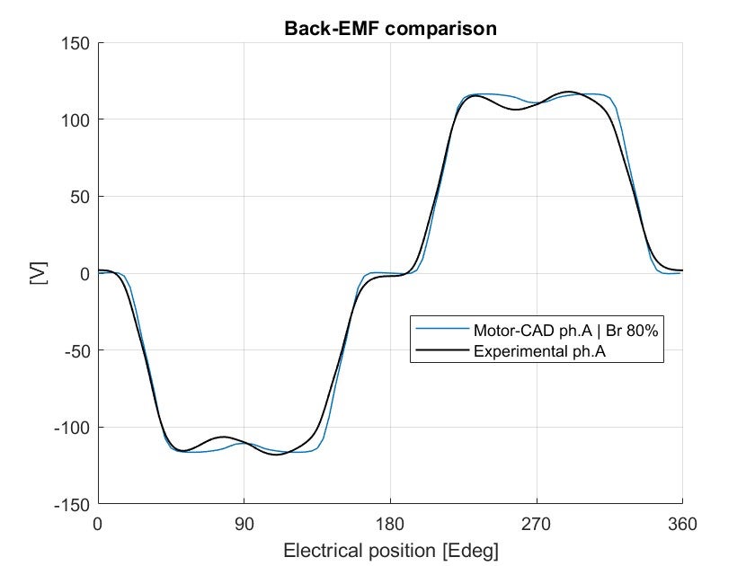
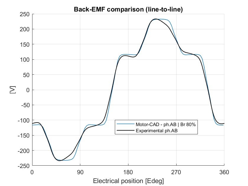
I attach the model and the comparison of the phase and line-to-line voltage on an Open circuit test, and what I noticed is:
- the motor-CAD curve has "holes" at 90° and 270°, while in the lab test these are shown before 90° and 270°
- this happens for every phase on every electrical cycle
- the Motor-CAD back-emf is the same as the one calculated by "Simcenter MAGNET" that has been previously used to simulate the motor
I uselessly tried to:
- add static and dynamic eccentricity
- slightly incline the magnetization of the PMs
- add a skew angle
- modify the .dxf file imported, making the magnet pockets different from each other (not symmetrical anymore)
- double check all the materials and the geometry
but I don't know if I'm still missing some other parameters to modify, so I ask you whether I'd better let it go or try to do something else.