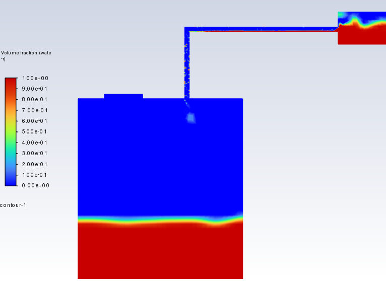
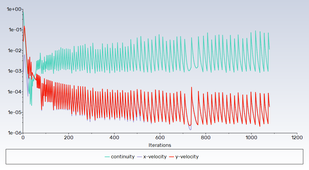
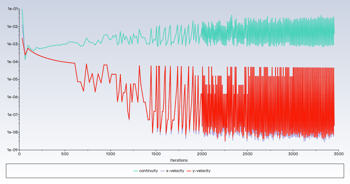
We have an exciting announcement about badges coming in May 2025. Until then, we will temporarily stop issuing new badges for course completions and certifications. However, all completions will be recorded and fulfilled after May 2025.
3D Design

3D Design

Topics related to Ansys Discovery and Ansys SpaceClaim.

Momentum Source Not Changing Flow Rate in a Closed-Loop Circuit

    • mohammad.nabil
      Subscriber

      I am 
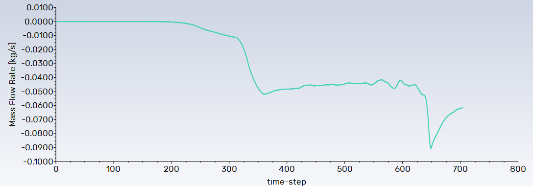
working on a closed-loop fluid circuit in ANSYS Fluent and using a momentum source to simulate a pump. However, despite applying the source term, the flow rate remains unchanged, and I don’t see the expected increase in velocity within the loop.


      Here’s what I have tried so far:

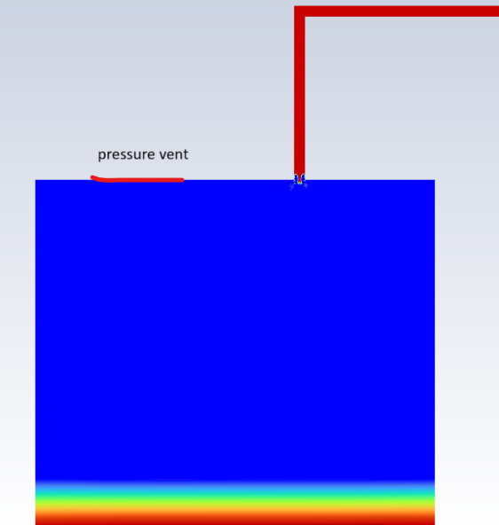
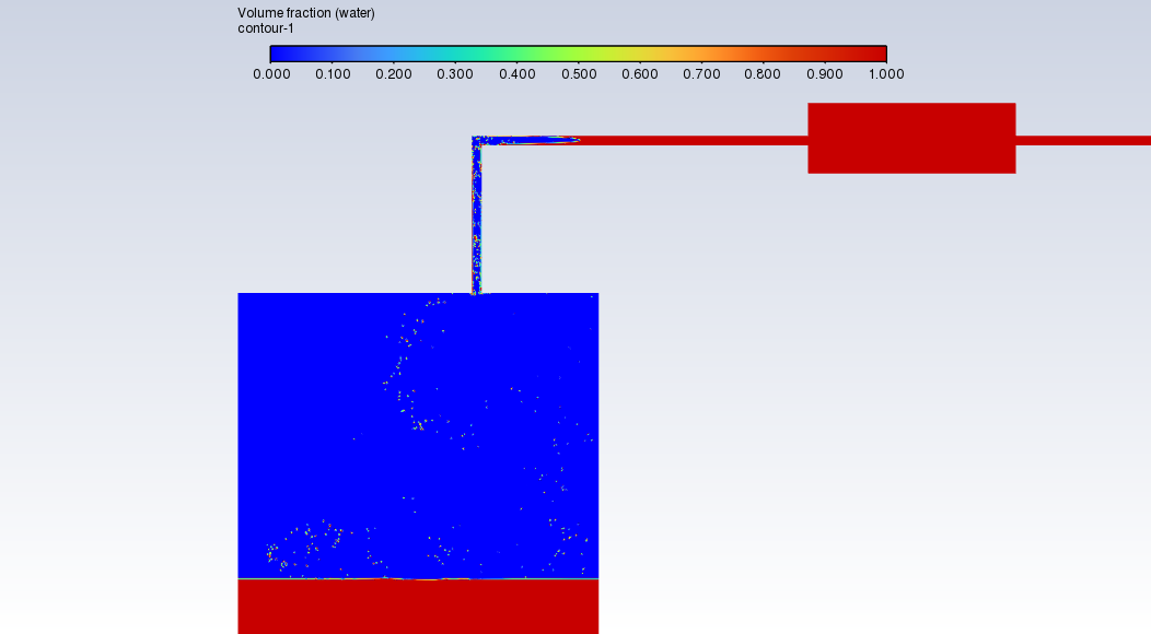
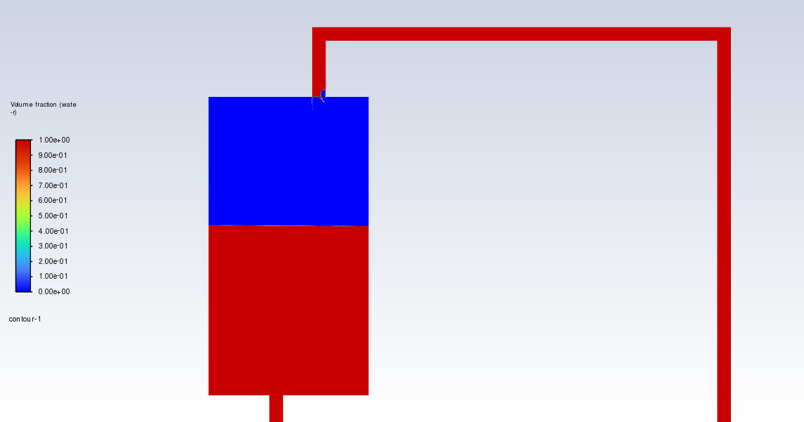
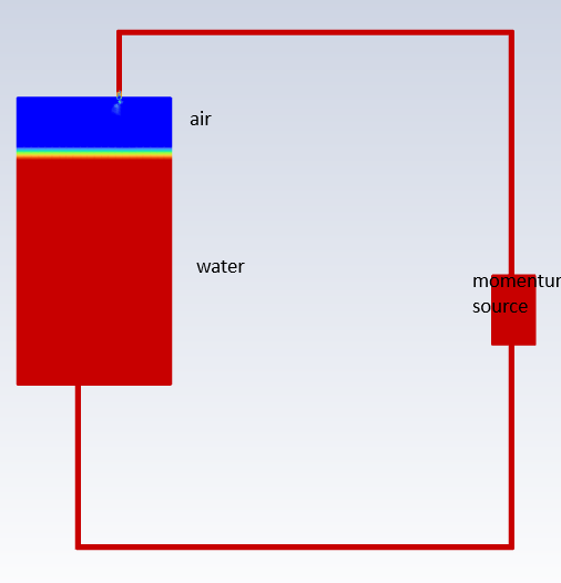
      • Applied the momentum source in the pump region in the image.
      • Increased the source term magnitude significantly, but no noticeable effect on the flow rate.
      • Checked boundary conditions—since this is a closed-loop system, there are no inlets or outlets, just walls. 

      I was expecting the momentum source to drive the flow, similar to how a pump would, but it doesn’t seem to be working. I have attached an image of my setup for reference.

      Has anyone encountered this issue before? Are there additional settings or considerations I should check?

      Any insights would be greatly appreciated!

      Thanks in advance.

    • Rob
      Forum Moderator

      You should get a flow, but as it's sealed and you may not have balanced the source with the loop pressure loss there's a good chance of winding speed up to infinity. 

    • mohammad.nabil
      Subscriber

      Thank you for your reply. 

      Indeed, after several iterations, the flow tends to reverse and move upward within the circuit. Additionally, the flow rate exhibits high-frequency fluctuations. How can I address this issue? I would appreciate any insights you could share.

    • Rob
      Forum Moderator

      You can try venting the air space. That should reduce pressure fluctuations and also anchors the solution back at the boundary pressure. 

    • mohammad.nabil
      Subscriber

      Thank you for your suggestion. I made a pressure outlet as you can see in the image. But I am still having reverse flow in the tube and flow rate fluctuation. Do I need to make an outer air domain? 

      I am applying VOF method with 0.0001/0.001 time step size.


    • Rob
      Forum Moderator

      No, I assume the backflow is set to air?  How well resolved is the nozzle? Do you actually need the loop, what's wrong with just pushing liquid into a chamber? 

    • mohammad.nabil
      Subscriber


      The backflow volume fraction for water is currently set to 0. Fluent also keeps showing warnings for reversed flow.

      I need the loop for further analysis. It is meshed with a resolution of 0.25 mm, and the loop diameter is 4.8 mm. 


    • mohammad.nabil
      Subscriber

      I am getting negative pressure at the end of the loop/ at the top of the reservoir. Since the pressure at the vent is 0, It is creating a back flow. Is there any way to solve the problem? 

    • Rob
      Forum Moderator

      Back flow is fine, and should be zero water. It's going to take some time for the system to settle down. For VOF you're meshing to resolve the free surface, and that will include any droplets that are formed. This is not going to be a small model. 

    • mohammad.nabil
      Subscriber

      The system settles down after 6000 iteration and the flow rate is also 200ml/min. Exactly the flow that I want. But it is sucking air into the loop. It is all back flow of air. Even if I change the direction of the momentum, the schenario does not change. What could be the reason? I keep monitoring the pressure at the top of the reservoir and it keeps a negative pressure of -0.48Pa/m^2. Is this the reason for back flow? 

    • Rob
      Forum Moderator

      Convergence? Equally, if the mesh isn't suitable and flow is too low then it's quite easy to get results like you have: water drains down the side and air rises. 

    • mohammad.nabil
      Subscriber

      Convergence is good. Flow is supposed to be 200ml/min. The tube diameter is 4.8 mm. and the reservoir tank width is 177mm. I am not sure if this is causing any issue. for the reservoir, it is meshed with 5mm element size and the tube is meshed with 0.25mm. skewness is like 0.58 at the interface region between the tube and the reservoir. Also orthogonality is a bit poor around that region. But average mesh quality is above the standard. 

      I am meshing it again with finer elements. But meanwhile I would appreciate your thoughts.  

    • Rob
      Forum Moderator

      It's difficult to say, was convergence good for all time steps? If the channel is 4.8mm and the reservoir modelled with 5mm cells do you expect to retain any droplets coming out of the nozzle? 

    • mohammad.nabil
      Subscriber

      The initial convergences. The whole geometry is now meshed with 0.25mm size elements. But the problem persists. 

    • Rob
      Forum Moderator

      OK, so convergence is numerically just about there but otherwise questionable. The near random droplets in the reservoir highlight the convergence problem. 

    • mohammad.nabil
      Subscriber

      Thank you for pointing that out. Could you suggest me any ways to fix that issue? I doubt its a meshing problem. 

    • Rob
      Forum Moderator

      Mesh & time step. With VOF you're tracking the free surface so any droplets need resolving - that means 5-10 cells over the droplet in some cases. There's a reason we added the VOF to DPM functions. 

    • mohammad.nabil
      Subscriber

      Thank you. I am going to definitely remind myself of this. I was worried about the stability. From a rough calculation I used CFL~0.073 but used explicit method. But I was not careful about the sensitivity of the VOF. 

      For now I have two  questions.

      1. How do I know what willbe the minimum surface area of the droplets so that I can adjust my mesh element size?
      2. Could you mention some references where I can go and read about this specific issue? 
    • Rob
      Forum Moderator

      1) You don't. We usually work out what we can afford to resolve and then set the VOF to DPM transition to be a little larger than that. 

      2) Not really. I'm only permitted to point you at Ansys materials (Learning is good) and things that are found from a search. Most of the public multiphase information is in Learning or the Ansys Learning Hub or documentation. 

    • mohammad.nabil
      Subscriber

      I meshed the region with very fine elements. I also decreased the time step sizes.
      I increased the diameter of the loop too. From 4.8mm to 15 mm. meshed it with 0.1mm elements. 
      Backflow is still occurring. The simulation is taking a long time due to the high-quality mesh, and it's still in the early stages. However, I'm not sure if things will change as it progresses. Is it because of boundary conditions? I have two momentum sources in the loop. Tow pressure outlet in the reservoir. 

      I would appreciate your guidance after this. 

    • Rob
      Forum Moderator

      How fast is the flow in the loop? Is there a scenario where the liquid can flow quickly enough down part of the pipe but leave space for the gas to rise? 

Viewing 20 reply threads
  • You must be logged in to reply to this topic.