-
-
February 21, 2023 at 9:15 am
tortju
SubscriberHi,
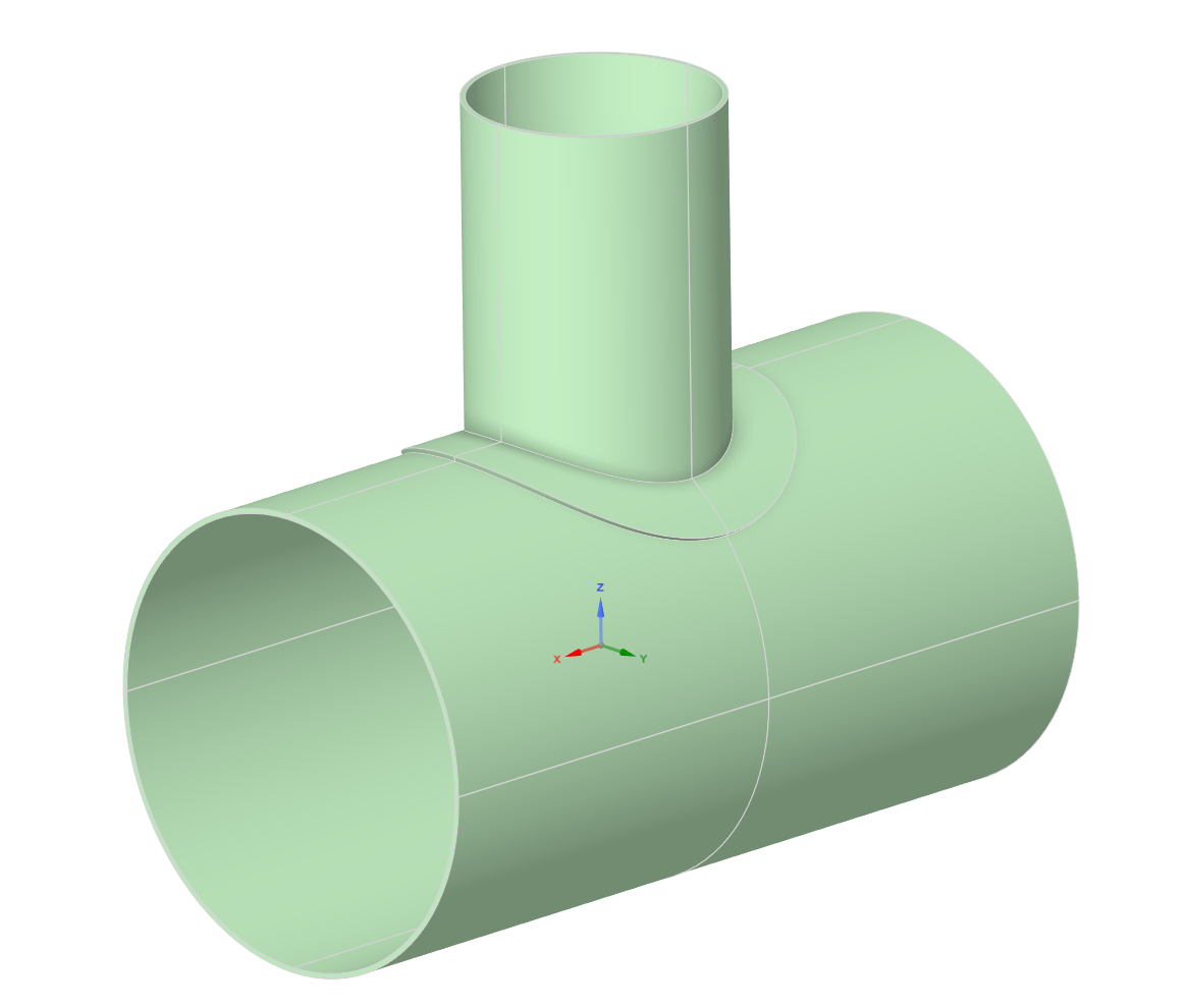
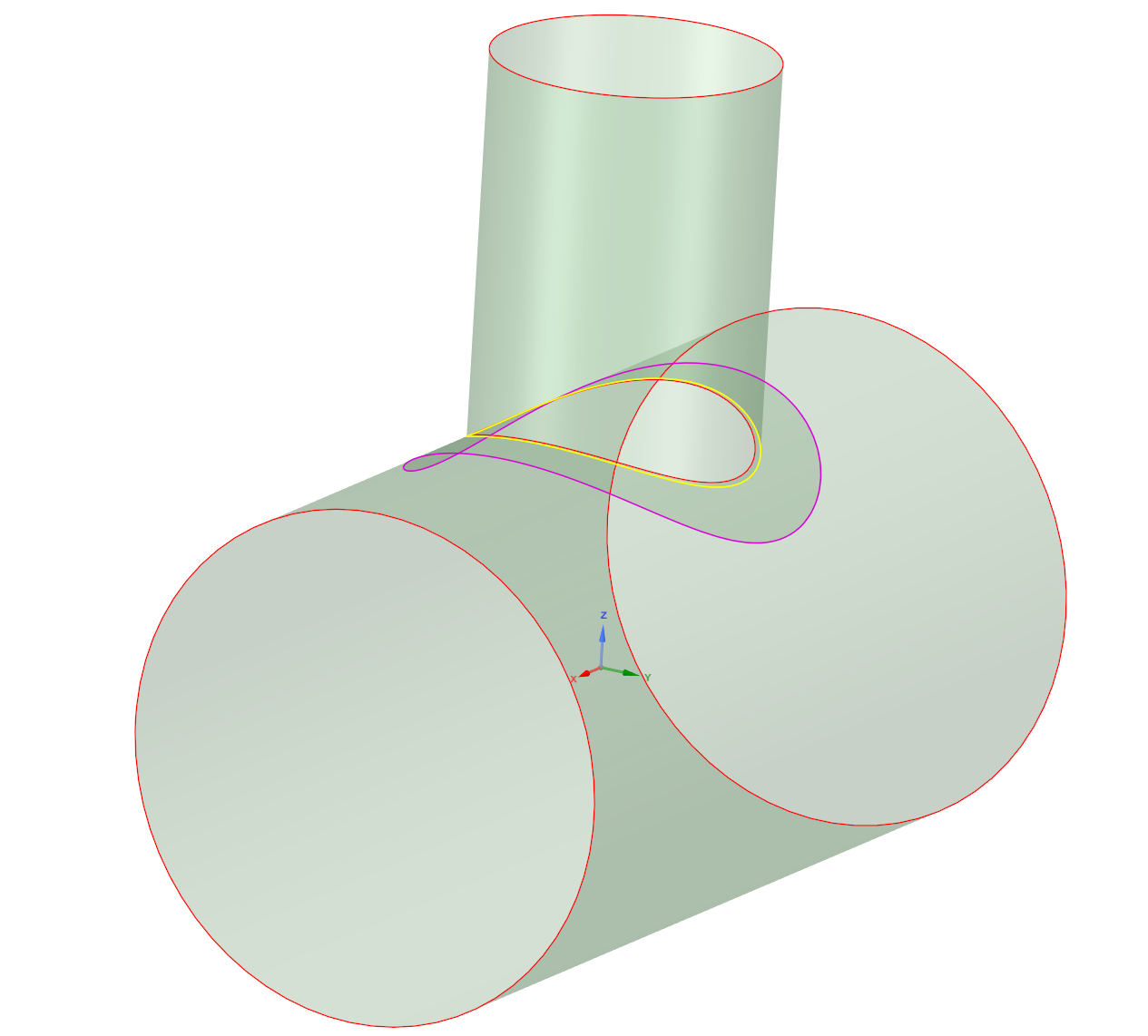
I am doing an analysis of a reinforced nozzled pipe in Ansys Mechanical. The main shell has an inner diameter of 1100 mm, while the nozzle has an inner diameter of 600 mm. All parts (shell, nozzle and reinforcement pad) have a thickness of 12 mm. I have regarded all parts as thin structures and they are therefore modelled as midsurfaces and with shell elements. Both the shell and nozzle are loaded with an internal outward pressure of 2,15 MPa and the end edges of the shell are fixed. All parts are modelled as S355 steel. The geometry from Spaceclaim are shown below (solid bodies only for visualization):
My question is how to model the contact between the reinforcement pad and the shell and between the reinforcement pad and the nozzle? The reinforcement pad shall be welded to the shell along the outer edge of the pad, while the nozzle (set-on type) should be welded to the shell along the end edge of the nozzle and to the reinforcement pad along the inner edge of the pad. I have tried to illustrate this in the attached figures. The welds are drawn as red lines.
I am thinking of modelling the welds as bonded contacts along the relevant edges. However, I think it may be wrong to model the entire contact surface under the reinforcement pad as bonded. This may instead be modelled as frictionless(?) or no separation (?) or something else?. Are there other advanced contact settings that should be considered here? The analysis won't run with some contact types.
-
February 21, 2023 at 10:46 am
peteroznewman
SubscriberConsider not using contact. In SpaceClaim, I assume the nozzle edge has been extended to meet the opening in the shell.
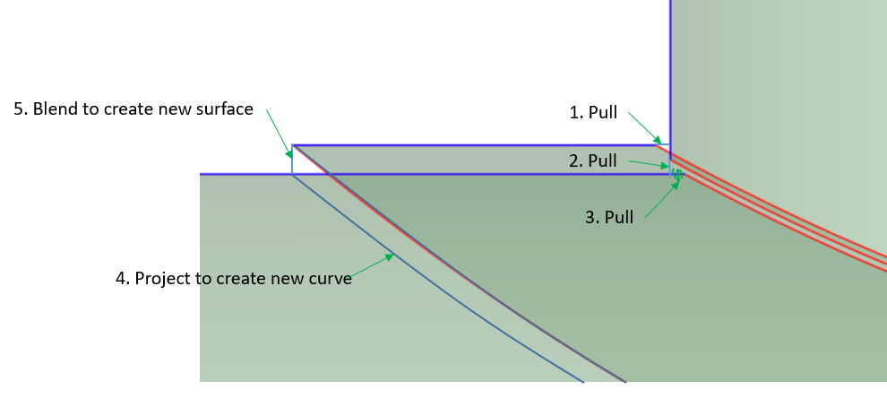
Extend the hole in the pad to touch the nozzle.
Project the outside edge of the pad onto the shell, then create a surface using the Blend tool (keyboard B) between the projected curve on the shell and the outer edge of the pad.
On the Workbench tab, use the Share button. The result is the nozzle, shell and pad are connected at the correct edges.
A conservative analysis would be to ignore any face-to-face contact between the pad and the shell.
-
February 21, 2023 at 1:23 pm
tortju
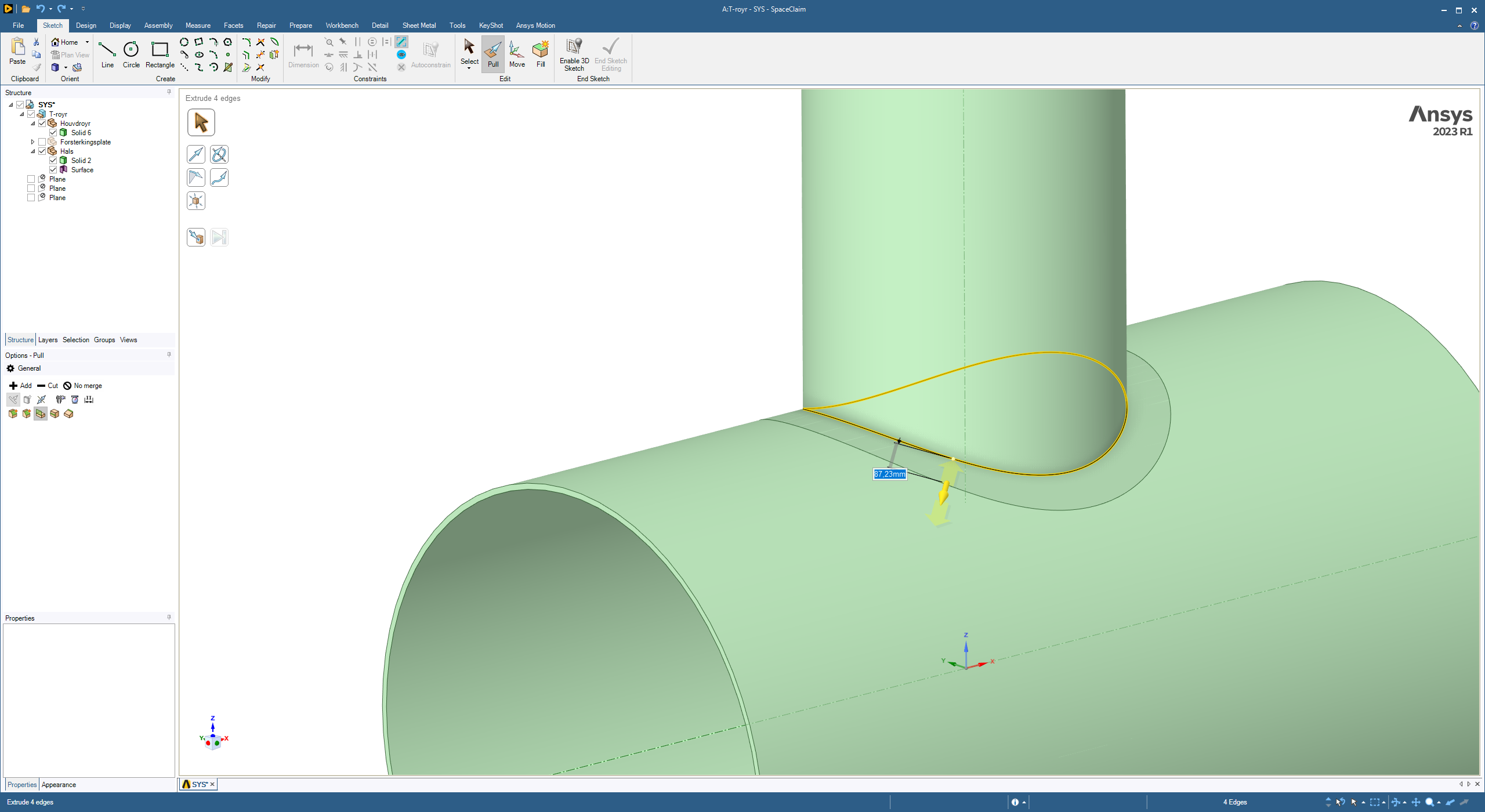
SubscriberThe model was first created in SpaceClaim using solids. The reinforcement pad was extruded along the shell surface from the insersecting edge between the nozzle and the shell:
The thickness was then pulled up to 12 mm. The resulting opening i the reinforcement pad was then deleted and the now closed reinforcement pad was split along the outer edge of the nozzle in order to make sure that no gap existed between these two.
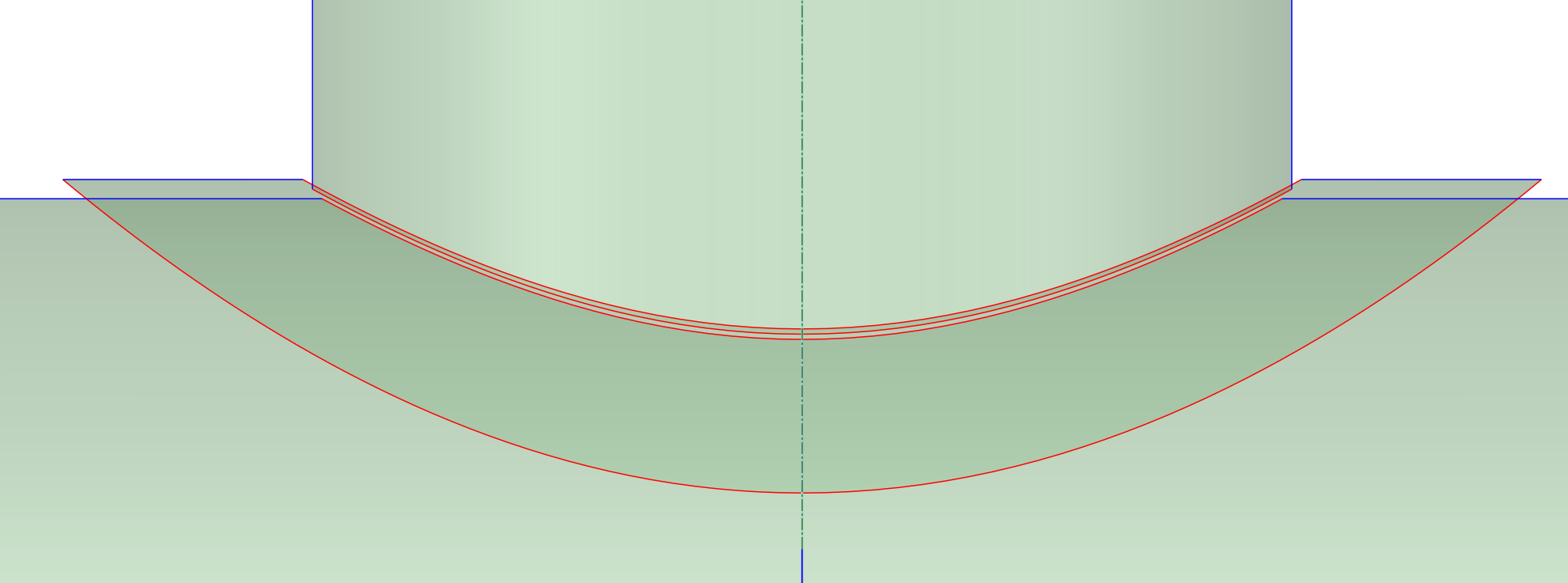
The solids in the model were then converted to midsurfaces using the "Midsurface" command under Prepare. After I created the midsurfaces I selected all of them and used the Share button as you described. This resulted in the following:
I guess what you mean would be to make sure all the edges in the screenshots above turn blue (except the two at the ends of the shell and the one at the end of the nozzle)? Can this be done from my current model?
In the current model the midsurfaces have assigned a thickness of 12 mm as a parameter. If I project the midsurfaces onto the shell as you suggest, wouldn't that make the reinforcement pad penetrate the shell when the thickness is assigned?
-
February 21, 2023 at 3:18 pm
peteroznewman
SubscriberIf you follow the directions given, material is created to reach the midsurface.
An equivalent model that would have similar results woud be to do step 4 above, and to project the edge of the pad onto the nozzle to create the edge that step 1 above creates. Then use edge-to-edge bonded contact to jump the gaps. In either case, the connection is made at the midsurface.
A better model is to copy/paste the outer surfaces of the shell and nozzle and the bottom surface of the pad. Now all the surfaces have edges that touch so there is no need to create a new surface, there are no gaps to close. In SpaceClaim when you click the Share button, you must reject sharing the surfaces and only share the edges so the pad does not merge with the shell. This may create the projection of the outer curve of the pad onto the shell. If not, do that manually. At the end, you need two coincident surfaces, one for the pad and one for the shell.
Then in Mechanical, since these surfaces are not midsurfaces, you must type in the 12 mm thickness manually, and you also select the offset to be Top or Bottom appropriately. After you mesh, turn on Shell Thickness and you can check that the offest has been correctly defined as it should look like the solid model.
-
February 22, 2023 at 9:23 am
tortju
SubscriberThank you for your thorough reply!
I simplified the model a bit (merging the already splitted bodies) such that the model now consisted of only three solids: the shell, the nozzle and the reinforcement pad.
After doing this I followed your suggestion of copying and pasting the outer surfaces of the shell and the nozzle and the bottom surface of the reinforcement pad. I rejected sharing the surfaces and I got the two coincident surfaces (no need for manual projection). I got the following result in SpaceClaim:
The different colors indicate how many edges/surfaces each edge are connected to, right?
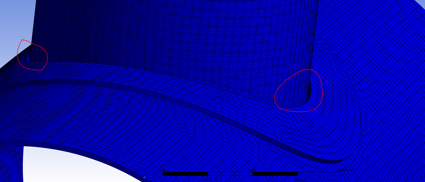
I followed your directions in Mechanical as well. The program suggested bonded contact between the bottom face of the reinforcement pad and the top face of the shell, but I suppressed this (no contacts used in the model). This appeared to work fine, but I noticed a gap appearing between the reinforcement pad and the nozzle on two opposite sides:
This doesn't appear to be any problem on the two other sides:
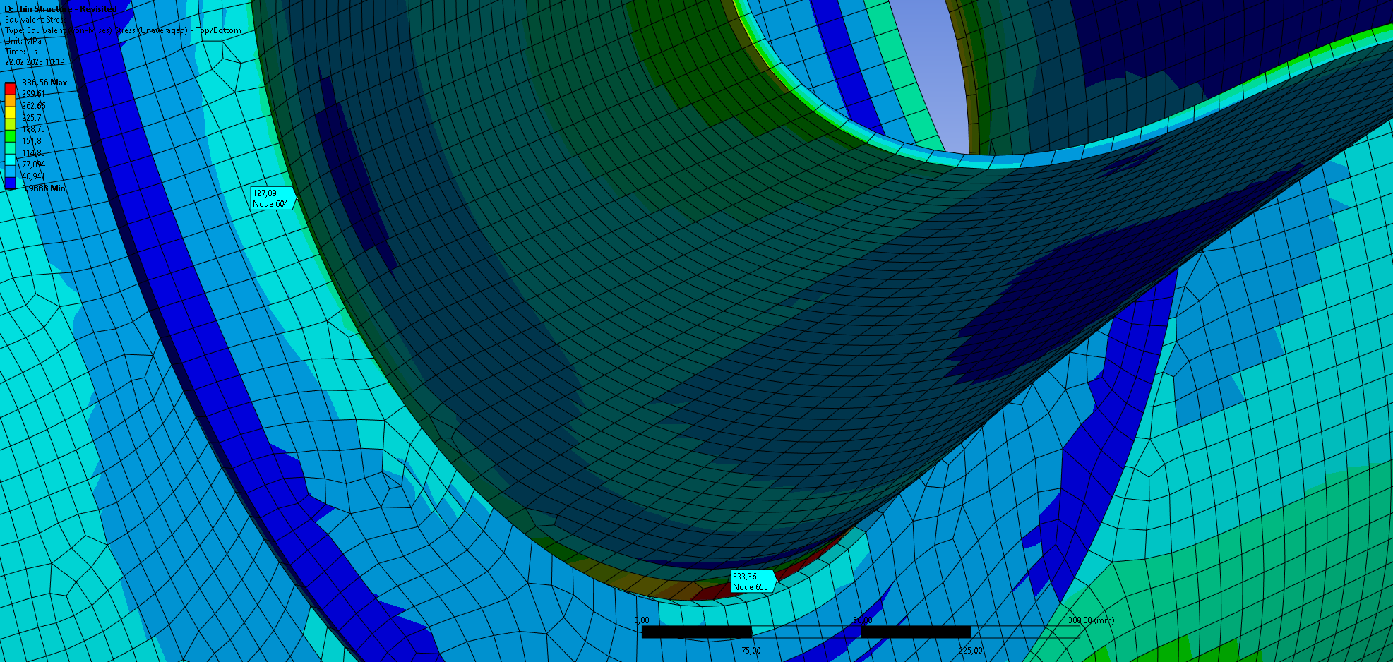
This may only be some kind of bad geometry visualisation, but I don't think so since this gap causes large stress concentrations in the equivalent stress results:
Do you have any suggestions on what may be the problem here? The edges seem to be shared correctly and the elements are nicely aligned over the connected edges.
-
February 22, 2023 at 12:03 pm
peteroznewman
SubscriberThe gap is just a visualization artifact. When thickness is visualized, Mechanical simply projects the face of the shell element along the normal vector. At the top of the shell, the normal of the pad elements point along the axis of the nozzle, so no visual gap is created, but on the side of the shell, the normal points out and a visual gap appears. Notice that when you turn thickness off, there is no gap.
The pad is properly connected as shown by the yellow and purple lines. A red line means no connection. The pad shows a red line on the ID hole. I suggest you use SpaceClaim, Split Body to split the pad with the nozzle and delete the thin surface at the ID, then you should just see a yellow line at the ID and no red line.
The stress concentration is real.
-
February 23, 2023 at 8:19 am
tortju
SubscriberThe explanation regarding the thickness visualization makes sense!
The inner diameter of the nozzle should be equal to the diameter of the hole in the shell (600 mm). If I split and delete the thin surface at the inner diameter the hole would become to large. I fixed this by copying and pasting the inner surface of the nozzle instead of the outer. Then in Mechanical I assigned the thickness of 12 mm in order for the nozzle to meet the reinforcement pad. The connections in SpaceClaim now looked like this:
I'm still not completely convinced regarding the stress concentration. The maximum stress appear to be increasing as I am refining the mesh. Maybe the stress concentration may be an artificial one due to a sharp corner singularity? On the other hand, this seems strange since the "sharpness" of the corner is the same all the way around the circular edge but the stress concentrations are only appearing on the two opposite sides. Do you have any suggestion on how to determine this? I can't find the convergence option for automatic mesh refinement. Maybe it is not available for shell elements?
-
February 23, 2023 at 3:25 pm
peteroznewman
SubscriberA shell model is an idealization of the true structure and part of the idealization is choosing what features to be approximated more than others. There are many ways to build a shell model of this structure. They will all have similar global stiffness behavior, but details of peak stress will differ depending on how the idealization was done.
There is a true stress concentration due to the sudden doubling of material thickness at that edge.
There may also be a stress singularity so that the stress will increase without limit as the elements get smaller. Use a Mesh Sizing control on that edge to create smaller elements and build a series of results to plot peak stress vs element edge length. Please reply with that data plotted out.
-
February 24, 2023 at 9:35 am
tortju
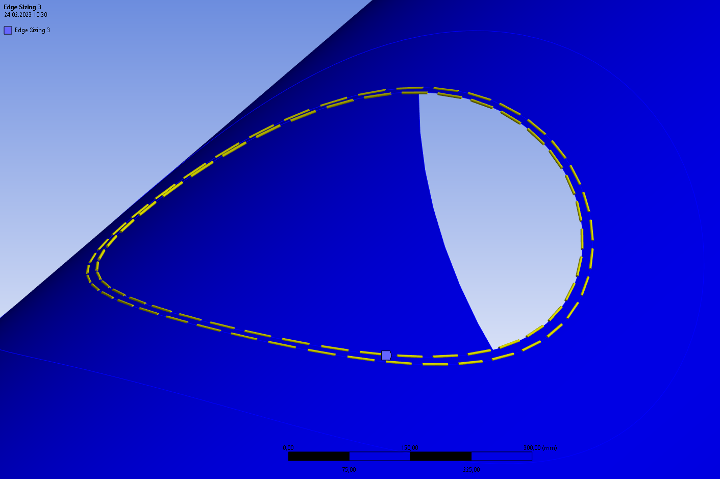
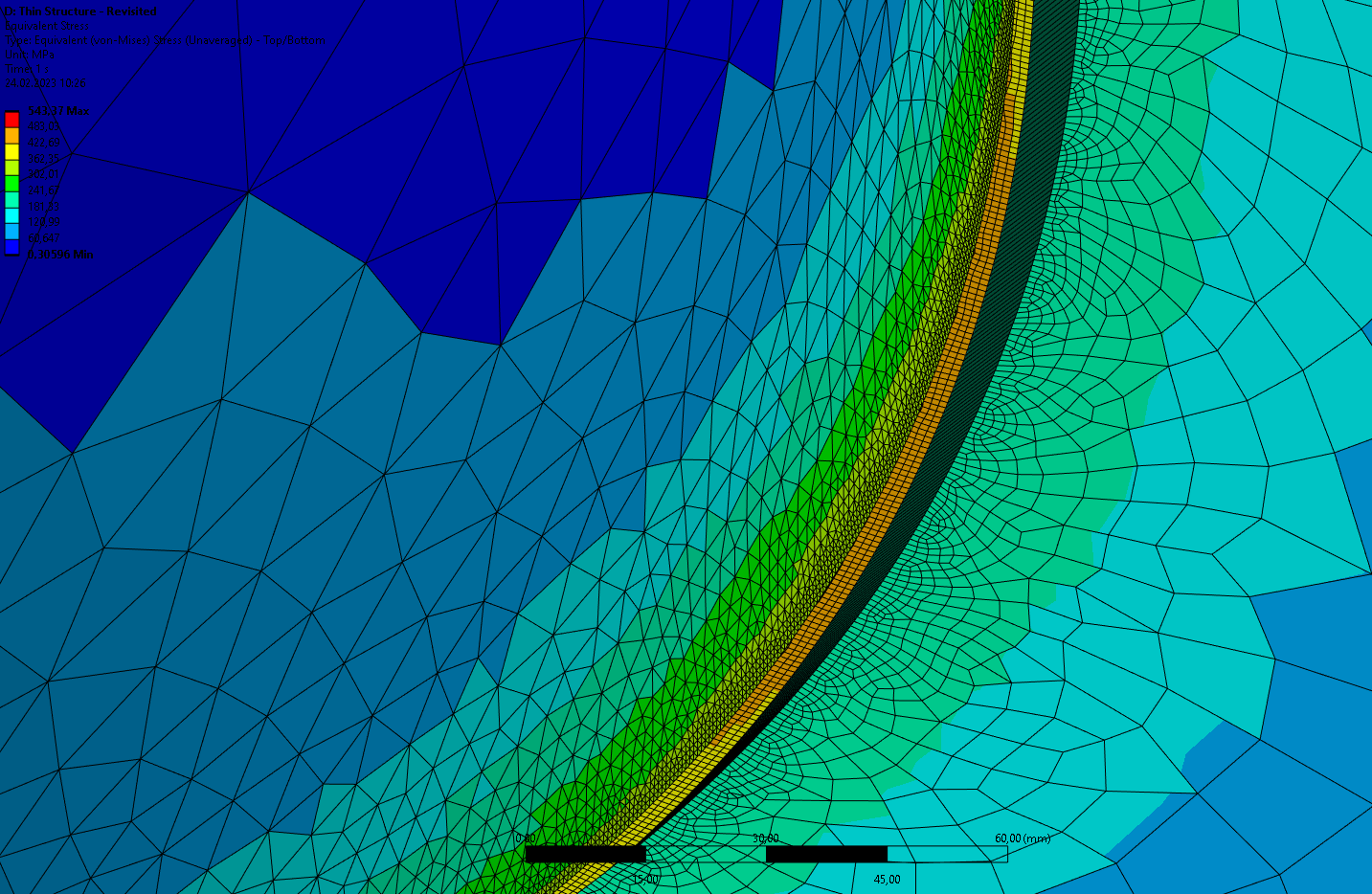
SubscriberI defined a global mesh size of 50 mm using the standard mesh component in the project tree. Then I defined an edge sizing on each of the outer surfaces of the shell like this:
From the inside of the shell:
From the outside of the shell:
I think the sudden change in stress (especially as seen from the inside) is a bit strange. The results are displayed as unaveraged.
Here is the plot of the peak stress vs the element edge length:
The large value only were found in only a couple of small elements. I think this value can be disregarded.
-
February 24, 2023 at 11:45 am
peteroznewman
SubscriberThere is no stress singularity at these edges based on the plot you show. If you plot the element edge size on a log scale, it will make it easier to see the points bunched up near zero.
-
February 24, 2023 at 11:57 am
-
- The topic ‘Modelling contact between reinforcement pad and shell/nozzle’ is closed to new replies.


-
4969
-
1644
-
1386
-
1242
-
1021

© 2026 Copyright ANSYS, Inc. All rights reserved.

