-
-
September 6, 2022 at 2:06 pm
marco.ballotta.2
SubscriberDear all,
I am using Ansys 2021 R1 and I would like to model my material to have different behaviour in tension and compression, as my experimental tests show. In particular, the Young modulus is different, but I also have two different stress-strain curves, one for tension and one for compression.
I heard that the cast iron material model may be useful, but I saw that there are two cast iron model (one in GRANTA database and one in general materials) so I don't know which to use, and also I used the isotropic multilinear hardening to input my tensile stress-strain curve but I don't know where to put the compressive stress-strain curve.
Do you know how to do it? I would really appreciate your help.
-
September 6, 2022 at 2:07 pm
marco.ballotta.2
SubscriberI did not specifiy, I am using Workbench and not the Mechanical APDL. -
September 6, 2022 at 11:02 pm
peteroznewman
SubscriberDear Marco,
The two Cast Iron materials in Engineering Data Sources (Granta and General) are linear elastic isotropic materials. They don’t have the Cast Iron material model.
Open ANSYS Help and go to the Home screen so you can browse down to the Mechanical APDL section. Open that and go to the Material Reference section, then in Rate Independent Plasticity, select the link to Cast Iron, which is section 4.4.7 and read about that material model. You will find that for this material model, the Young’s Modulus is the same for tension and compression. It is the yield surface that is different for tension and compression.
Unfortunately, ANSYS hasn’t put Cast Iron in the Plasticity section of the Engineering Data Toolbox, which means you can’t define the constants for it in Workbench, you will have to insert a Command object into your Mechanical model. Fortunately, the Help section includes an example of the APDL code that you would put into the Command object.
If you need further help, reply with your question and hope someone else answers, I have reached the limits of my experience on this topic.
-
September 7, 2022 at 7:59 am
marco.ballotta.2
SubscriberThank you very much Peter, you have been really precious. I will surely try what you suggest.
-
September 7, 2022 at 4:14 pm
marco.ballotta.2
SubscriberHello,
I did what @peteroznewman suggested and I created my code, that I am posting:
/prep7mp, ex, 1,3000 !Elastic modulusmp,nuxy, 1,0.4 !Poisson ratio!Define cast iron modelTB,CAST,1,,,ISOTROPICTBDATA,1,0.1 !Plastic poisson ratioTB,CAST,1,1,7,TENSIONTBTEMP,20TBPT,0,0TBPT,0.007055167,82.24TBPT,0.00783981,84.93375TBPT,0.008905017,87.6605TBPT,0.009870315,90.3875TBPT,0.012339927,93.267TBPT,0.016915443,96.906TB,CAST,1,1,5,COMPRESSIONTBTEMP,20TBPT,0,0TBPT,0.03855,40.95TBPT,0.077985,69.3TBPT,0.103,88TBPT,0.1345,102TBPT,0.155322,108The solution does not converge though, and after few minutes it gives me an "unknown error", so I checked the solution information and there were 200 warning messages like this one:*** WARNING *** CP = 230.641 TIME= 18:06:35
The material solution failed for element 114292 with material 1.about 4 messages for each element number. Why does it do it?Thank you -
September 7, 2022 at 8:38 pm
peteroznewman
SubscriberOne caution when working with APDL code in Workbench, where you are free to change the Units to other systems. The APDL code you put in is just numbers. The numbers don't change when you change Units like they do in Engineering Data. That means you should have a comment in your code to remind yourself what unit system is to be used for solving with that code. Under Analysis Settings, you can change each analysis system to always solve with a manually configured, fixed units selection that will be used no matter what Units are set in Workbench or Mechanical.
-
September 8, 2022 at 1:00 am
peteroznewman
SubscriberDear Marco,
When I look at the code in Example 4.20, I see the TBPT command has two commas after TBPT and the first row has zero plastic strain and a yield stress.
TB,CAST,1,1,5,TENSION
TBPT,,0.000E-00,0.813E+04
TBPT,, 1.13E-04,0.131E+05
When I look at your code, it doesn’t have two commas and the first row doesn’t have a yield stress to go with the zero plastic strain.
TB,CAST,1,1,7,TENSION
TBTEMP,20
TBPT,0,0
TBPT,0.007055167,82.24
It is very important to pay attention to small details like this. I added a row for the zero plastic strain point and made up a number for the yield stress. Also, always use a decimal point on real numbers. I don’t know if APDL corrects this, but when I use NASTRAN, that is unforgivable.
TB,CAST,1,1,7,TENSION
TBTEMP,20.
TBPT,,0.,2.0
TBPT,,0.007055167,82.24
TBPT,,0.00783981,84.93375
I like to create a unit cube model to test out material models. In this case, I have made a 10 mm cube, so the area of the cube is 100 square mm. I mesh this cube with a single linear element, so my model has only 8 nodes.
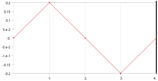
One 3 faces, I set the normal displacement to 0. On one face, I apply a normal displacement. I applied a +/- 0.2 mm sawtooth profile.
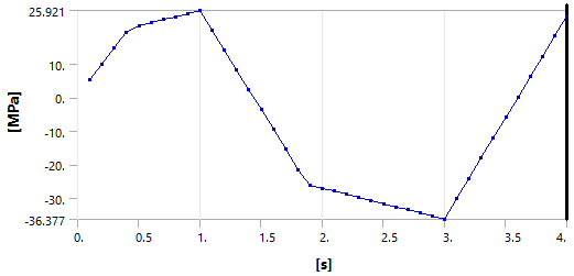
I plot the Normal Stress and see the material going platstic at different levels of stress.
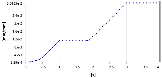
Below is the Accumulated Equiv. Plastic Strain (which is always positive).
Here is a link to my ANSYS 2021 R1 archive using a modified version of your code: https://jmp.sh/N9fJI5m
-
September 8, 2022 at 3:33 pm
marco.ballotta.2
SubscriberHello Peter,
thank you for the tips, I probably forgot the commas when I copied&pasted the code. I fixed this and I also put the decimal point as you suggested.
For what concerns the unit system, I always use the N, mm, mV, mA, °C system (so E and stresses in MPa) as I am from Europe, and I always switch these settings on when I use Workbench to make sure the results I want are consistent. I appreciate you reminding this because this is a typical error I would do :)
I run the code on my model, and everything seems to work nice! I really have to thank you, this is a great improvement for my mater's thesis.
Greetings
-
September 30, 2022 at 11:03 am
marco.ballotta.2
SubscriberHello Peter
I have a doubt regarding the input data. I saw that, in Abaqus, the compressive yield stress has to be greater than the tensile yield stress, otherwise an error message occours. This is because the cast iron model is implemented with the cast iron flow potential (like specified here https://classes.engineering.wustl.edu/2009/spring/mase5513/abaqus/docs/v6.6/books/usb/default.htm?startat=pt05ch18s02abm24.html).
My material is a bit difficult to inteprete, but the compressive behaviour suggests a compressive yield stress that is lower than tensile yield stress. This doesn't create an error in Ansys. Is this still correct though, can I use the cast iron model this way? It is the only way I have to model a materiale that have different behaviour in tension and compression.
Do you also know how to find the plastic poisson's ratio? I have a polimeric material, but on the internet I cannot find any data, even through all my academic and university resources.
Many thanks
-
September 30, 2022 at 4:18 pm
peteroznewman
SubscriberPlease show the overlay of the experimental stress-strain data with the model stress-strain data. Make sure to convert the experimental stress-strain data from Engineering Stress and Strain to True Stress and Strain.
If the model is an accurate representation of the experimental conditions, the Force vs Displacement of the experimental data can be overlaid on the Force vs Displacement of the model data. In this way, there is no need to convert.
From the Ansys material reference manual in the Cast Iron section, regarding plastic Poisson’s ratio is this paragraph:
The plastic Poisson’s ratio is the absolute value of the ratio of the transverse to the longitudinal plastic strain under uniaxial tension. It determines the amount of volumetric expansion during tensile plastic deformation. For plastic Poisson’s ratio = 0.5, the tensile flow potential reduces to the von Mises potential. The tensile flow potential gives a nonassociated flow model and results in an unsymmetric material stiffness tensor.
Some Tensile test machines have optical instrumentation to track the dot pattern sprayed on the sample. Can that data be used to compute the volumetric expansion during tensile plastic deformation?
-
September 30, 2022 at 4:37 pm
marco.ballotta.2
SubscriberThanks for your responde Peter,
maybe I haven't been precise on the problem. I am currently doing static structural simulations in Workbench on a real-world object (a sheave) with its loads and constraints. Because there is a lot of compression in the model, and the material may yield locally, I wanted to include in the model data the behaviour from stress-strain data, and I created a command APDL as you saw before. I took the stress-strain curve from literature for the tensile part, and from a datasheet for the compressive part. All I have is a graph in excel with a bunch of points. Maybe you were thinking that I am doing uniaxial test simulation on Ansys but unfortunately I am doing something more "practical", as to say.
The data in my excel, which are the points that are in the APDL code, have been transformed in True Stresses and True Strains so from that point of view it is correct.
I don't know if with this information you can help me with my doubts. I am doing some tests in the lab in some weeks so I will have the stress-strain curves with precise data. About your last question, I really don't know, I am only a student and I have never been in the lab doing tests :')
Eventually, thank you for your time, I really appreciate it.
-
July 15, 2023 at 7:33 am
murad Bsharat
Subscriber -
July 15, 2023 at 8:00 am
murad Bsharat
SubscriberHello Peter
I have two problem ,
- I want to define concrete material with compression and tension with softening (damage plasticity ) - mander concrete model - how we can do.
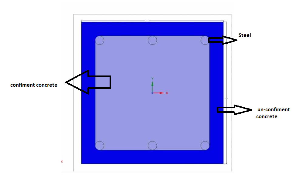
- i'm want define profile section (column and beam )in spaceclaim as line conten three materiales ( steel , confiment concrete and unconfiment concrete )
-
July 15, 2023 at 8:09 am
murad Bsharat
SubscriberHello Peter ,
Note , I have data (stress and strain for materials) . but don't know how I can use ANSYS to define it
-
- The topic ‘Modeling different behaviour in tension and compression’ is closed to new replies.


-
4618
-
1530
-
1386
-
1209
-
1021

© 2025 Copyright ANSYS, Inc. All rights reserved.


