-
-
April 27, 2022 at 9:11 am
Khanhminh
SubscriberI analyzed corrosion RC beam so I used the element Combin39 to model the bond between concrete and steel.
This element required force and deflection along the length X-axis (axis of the beam). I transform the bond-slip (MPa-mm) to force-displacement (N-mm) to enter a value in real constant.
I validated exactly the load-deflection of RC beams from the simulation model and experimental program.
Nevertheless, I would like to understand how Ansys transforms force-deflection input data into a stress-strain for the element to solve the problem. Since FEM generally requires stress and strain. Please explain relates the length of the element or related force-stress. Thank you for considering.
May 4, 2022 at 10:09 pmSheldon Imaoka
Ansys Employee
COMBIN39 is just a node-to-node element. Thus, the node is not directly associated with an area or volume - that is why we use force vs. deflection in its definition. It is just basically a spring, like K*x=F, similar to the FE matrix equation we solve [K]{x}={F}.
When you have solid elements, for example, the integration point for the constitutive relationship is associated with a 'volume', so that is why you end up with stress vs. strain definition instead. From the constitutive relationship (stress vs. strain) and element properties, we go to a form of [K]{x}={F}. So your comment is reversed - we do not go from COMBIN39 force-deflection curve to stress vs. strain but do the opposite; everything is transformed to stiffness [K], deformation {x}, and forces {F} to solve as a matrix equation.
If you have traction vs. separation (bond-slip), did you intend to use something like a cohesive zone model? If your reinforcement is modeled as a beam element (single node describing cross-section), then the COMBIN39 is suitable, and you need to estimate the area associated with a node to convert the bond-slip relationship to force-displacement. If, however, your reinforcement is a solid, then you may want to look at the cohesive zone model instead (see Fracture Analysis Guide, Sections 3.5 and 3.6 on modeling interface delamination). The cohesive zone model is defined as a traction-separation law (units of stress vs. displacement, such as MPa - mm).
May 5, 2022 at 4:33 amKhanhminh
SubscriberThank you so much for your information
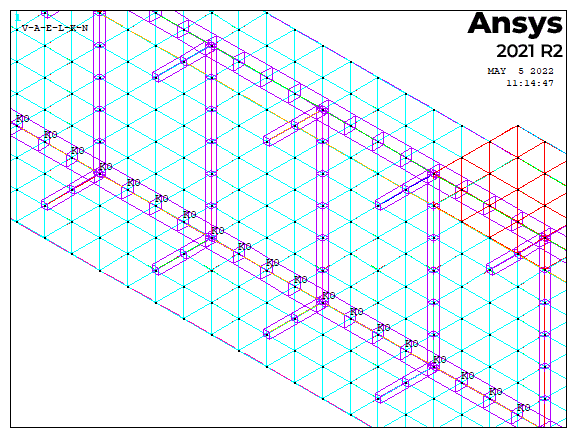
Since I used the link 180 and solid65 to model the reinforce and concrete respectively. I didn't consider the traction vs separation. So is there available to model the Combin39 at the coincidence node like in the following picture? (You may see the letter KO at the node)
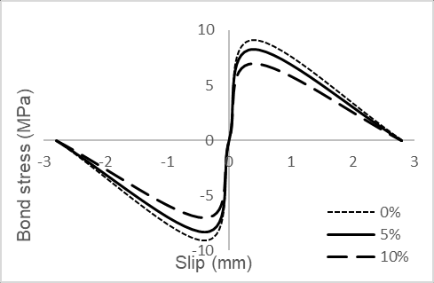
Here I only consider the corroded tensile bar. The model bond-slip model according to fib Model code 2010 Here is bond stress (Mpa) then I convert to force F=3.14*d*L*bond (N)
So the input data in the real constant, I simply use the Force converted and value slip on the graph. Is that any inaccuracy?
Once again very thank you.


May 10, 2022 at 3:16 pmSheldon Imaoka
Ansys Employee
By using total area (pi*diameter*length), you're assuming that the bond separates around the entire surface at once. I can't comment whether or not this is a reasonable assumption for your application, but I just wanted to point this out. Of course, if you model the reinforcement as a LINK180 element, you don't have any 'partial' area but need to treat the bond around the circumference since it is just a single node, not an actual surface, so what you did seemed reasonable for the modeling you used, but I just wanted to point out that you're treating the failure to occur around the entire circumference of the reinforcement rather than a smaller area, which may happen in real life.
Regards Sheldon
Viewing 3 reply threads- The topic ‘MODEL BOND BETWEEN CONCRETE AND STEEL USING COMBIN39 ELEMENT’ is closed to new replies.
Innovation SpaceTrending discussions- LPBF Simulation of dissimilar materials in ANSYS mechanical (Thermal Transient)
- Real Life Example of a non-symmetric eigenvalue problem
- How can the results of Pressures and Motions for all elements be obtained?
- BackGround Color
- Contact stiffness too big
- Element Birth and Death
- Python-Script to Export all Children of a Solution Tree
- Which equations and in what form are valid for defining excitations?
Top Contributors-
4597
-
1495
-
1386
-
1209
-
1021
Top Rated Tags© 2025 Copyright ANSYS, Inc. All rights reserved.
Ansys does not support the usage of unauthorized Ansys software. Please visit www.ansys.com to obtain an official distribution.
-


Ansys Assistant

Welcome to Ansys Assistant!
An AI-based virtual assistant for active Ansys Academic Customers. Please login using your university issued email address.
Hey there, you are quite inquisitive! You have hit your hourly question limit. Please retry after '10' minutes. For questions, please reach out to ansyslearn@ansys.com.
RETRY


