
TAGGED: deformation, explicit-dynamics, milling, strain
-
-
December 22, 2020 at 1:24 pm
Rekasi1996
SubscriberHello all!
I would like to simulate a milling process for my thesis. It's almost already done, the material in case of the tool is titanium, and in case of the workpiece is a general steel. I used two Velocity to define the proper movements. The tool is rotating with 5000 [RPM], and the workpiece is moving forward with 34 [mm/s]. After the solution process I have got these results.
December 24, 2020 at 2:49 pmpeteroznewman
SubscribernDeformation is the distance of the node from its starting point. Insert three Directional Deformations which measure the three signed components of distance of the node from its starting point. The values of Y will be close to zero. The values of X and Z will oscillate between +/- the radius of the tool depending on the angle of the tool since the start of the simulation.nDecember 27, 2020 at 3:37 pmSubscribernFirst of all, thank you very much for your answer. nTo sum it up, in my case the total deformiation is not an interesting result, because the tool is rotating. I would like to get an average value of the deformation in case of the tool. How can I export those values of deformation which are not affected by the moving (tool diameter is 10 mm)?nHere is the directional deformation in case of Z axis for example.n Thank you in advance!n
December 27, 2020 at 7:48 pmSubscribernIn CAD, is the tool centered on the Y axis? Does the tool have a vertex on the Y axis?nIf not, move the tool onto the Y axis and add a plane or two in CAD to split the edge or face to create a vertex at the center of the tool on the Y axis.nRequest output of that vertex of the signed Z deformation.nRequest output of that vertex of the signed X deformation.nThose plots show the deflection of the tool tip while it is cutting.nDecember 31, 2020 at 7:25 amSubscriberArray nI can solve this problem with a new coordinate system. I defined one C.S. which is connected to the tool. The Y is equal with the axis of the tool. n
Thank you in advance!n
December 27, 2020 at 7:48 pmSubscribernIn CAD, is the tool centered on the Y axis? Does the tool have a vertex on the Y axis?nIf not, move the tool onto the Y axis and add a plane or two in CAD to split the edge or face to create a vertex at the center of the tool on the Y axis.nRequest output of that vertex of the signed Z deformation.nRequest output of that vertex of the signed X deformation.nThose plots show the deflection of the tool tip while it is cutting.nDecember 31, 2020 at 7:25 amSubscriberArray nI can solve this problem with a new coordinate system. I defined one C.S. which is connected to the tool. The Y is equal with the axis of the tool. n After that, I have defined a new Directional Deformation, with the new coordinate system.n
 And it is almost good, because when the tool is moving than the coordinate system is following that. Is it possible that we define a coordinate system which is rotating with the tool? Because in this case the rotation not affects the deformation results. I tried to connect the coordinate system to the tool but I didnt find any good solution for that. It should be good if I get a deformation which are not affected by the rotation. I have to show this results in my thesis.nThanks for your help again! n
December 31, 2020 at 3:49 pmSubscribernYour image shows the Directional Deformation of the Body that has a maximum value of 10 mm. I suggested you select a Vertex at the tip of the tool, right on the Y axis. Did you do that? That vertex will have a zero output before cutting begins, and a very small output while cutting. Is that not sufficient for your needs?nTry putting a Revolute Joint to Ground and scope it to the back circular face of the tool. That will put a Coordinate System on the Tool that rotates with the tool. Maybe you can Probe Joint Displacement under the Solution branch.nJanuary 4, 2021 at 6:46 pmSubscriberArray nI have tried your suggestion (vertex at tip of tool) and it works but I would like to shown the deformation for example along the edge of tool. I think your suggestion rather describe the buckling of the tool. Please correct me if I'm wrong. n
And it is almost good, because when the tool is moving than the coordinate system is following that. Is it possible that we define a coordinate system which is rotating with the tool? Because in this case the rotation not affects the deformation results. I tried to connect the coordinate system to the tool but I didnt find any good solution for that. It should be good if I get a deformation which are not affected by the rotation. I have to show this results in my thesis.nThanks for your help again! n
December 31, 2020 at 3:49 pmSubscribernYour image shows the Directional Deformation of the Body that has a maximum value of 10 mm. I suggested you select a Vertex at the tip of the tool, right on the Y axis. Did you do that? That vertex will have a zero output before cutting begins, and a very small output while cutting. Is that not sufficient for your needs?nTry putting a Revolute Joint to Ground and scope it to the back circular face of the tool. That will put a Coordinate System on the Tool that rotates with the tool. Maybe you can Probe Joint Displacement under the Solution branch.nJanuary 4, 2021 at 6:46 pmSubscriberArray nI have tried your suggestion (vertex at tip of tool) and it works but I would like to shown the deformation for example along the edge of tool. I think your suggestion rather describe the buckling of the tool. Please correct me if I'm wrong. n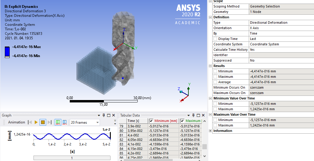 nTo be honest, I have tried your second idea of coordinate system topic. But in one case the simulate cannat solve, other case I cannot use those coordinate system which are created by joint to get the right deformations.nnThanks again! n
January 4, 2021 at 10:57 pmSubscribernFor the node on the Y-axis, I would not say it is for buckling. As the workpiece moves toward the tool, the cutting forces deflect the tool tip.nI don't know if the joint idea will work, it was just something to try.nViewing 7 reply threads
nTo be honest, I have tried your second idea of coordinate system topic. But in one case the simulate cannat solve, other case I cannot use those coordinate system which are created by joint to get the right deformations.nnThanks again! n
January 4, 2021 at 10:57 pmSubscribernFor the node on the Y-axis, I would not say it is for buckling. As the workpiece moves toward the tool, the cutting forces deflect the tool tip.nI don't know if the joint idea will work, it was just something to try.nViewing 7 reply threads- The topic ‘Milling simulation question’ is closed to new replies.
Innovation Space Trending discussions
 Top Contributors
-
peteroznewman
 4818
4818 -
scabo
 1587
1587 -
Dennis Chen
 1386
1386 -
javat33489
 1242
1242 -
Shyam Prasad V Atri
1021
Top Rated Tags
© 2026 Copyright ANSYS, Inc. All rights reserved.
Ansys does not support the usage of unauthorized Ansys software. Please visit www.ansys.com to obtain an official distribution.
-


The Ansys Learning Forum is a public forum. You are prohibited from providing (i) information that is confidential to You, your employer, or any third party, (ii) Personal Data or individually identifiable health information, (iii) any information that is U.S. Government Classified, Controlled Unclassified Information, International Traffic in Arms Regulators (ITAR) or Export Administration Regulators (EAR) controlled or otherwise have been determined by the United States Government or by a foreign government to require protection against unauthorized disclosure for reasons of national security, or (iv) topics or information restricted by the People's Republic of China data protection and privacy laws.


