TAGGED: -Structured-Meshing, ansys-cfd, fluent-mesh, fluid, mesh, meshing
-
-
May 31, 2023 at 3:25 pm
bbk
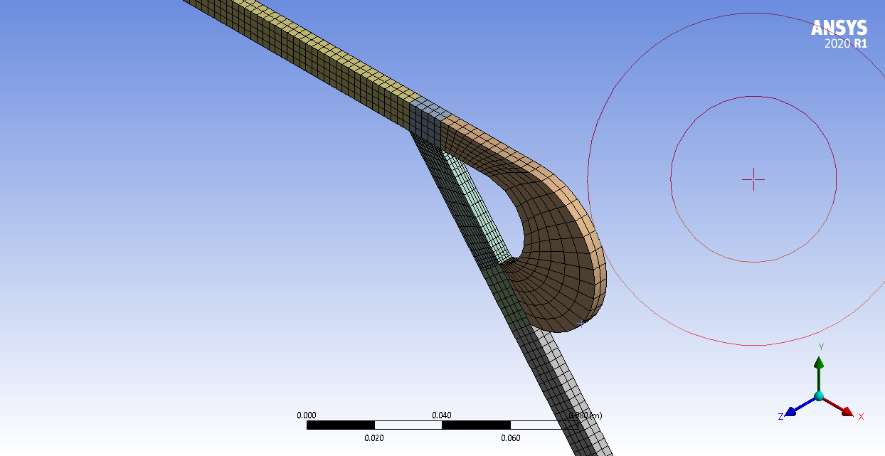
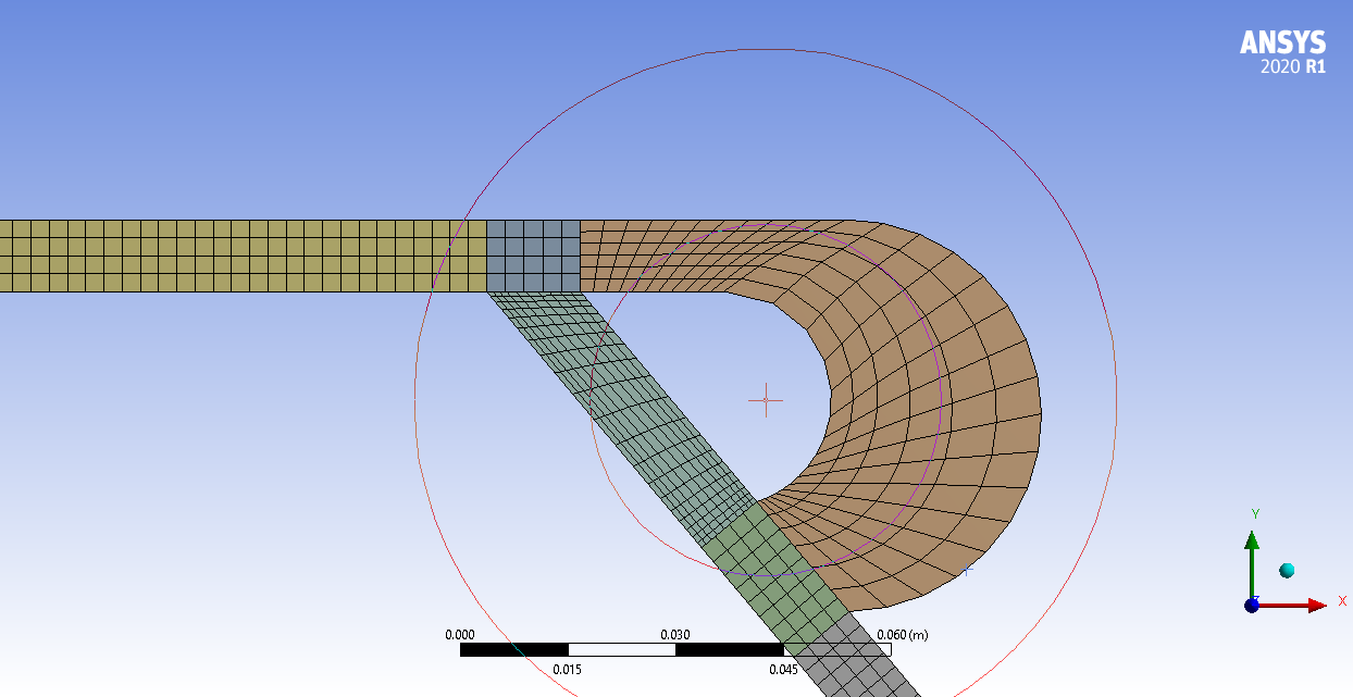
SubscriberI have a complex(?) 3D fluid domain that I have been trying to properly mesh for CFD analysis on Fluent. I generated such a sample mesh structure displayed from a side view in the picture. Being aware of the fact that it is not well structured.
As you can see in the pictures, I want to better capture results at sharp zones in the domain. I add inflation feature along the walls, but they end up having low quality. How can I make my entire domain well structured, if needed, other than refining my entire domain?
-
May 31, 2023 at 7:09 pm
Federico
Ansys EmployeeHello,
Looking at your second figure, I would suggest setting the sizings to be more uniform. For example, you could set Edge Sizings (on both +/- Z sides) to avoid having any jumps in sizes in the different regions.
-
June 1, 2023 at 2:29 pm
bbk
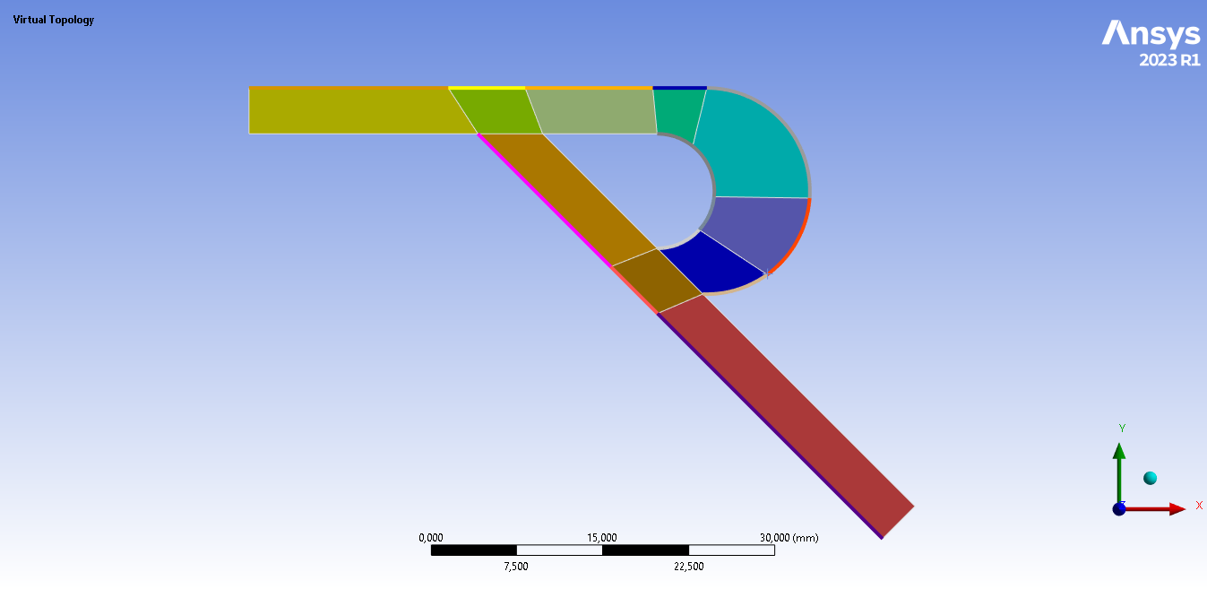
SubscriberHow can I deal with this "jump in sizes"? That is, I dissected my domain and even tried to utilize "share topology" option in "Design Modeler" tool. However, it is still of no avail. By the way, I am using "Design Modeler" since it is more convenient for parametric design study for me compared to SpaceClaim alternative.
-
-
June 1, 2023 at 7:00 am
NickFL
SubscriberAre you totally against triangles? Both Fluent and CFX have no trouble with them and it would save you time decomposing your domain.
The main goal when slicing the domain is to get volumes that look similar to a cube. The large curved area that you have, you can see the mesh is of poor quality. That is because the mesher is taking a square and bending the edges into a half circle. A better approach would be to slice and dice it until the resulting faces are only curved a bit.
Is this a simplified version of a Tesla valve? They seem to be all the rage currently.
-
June 1, 2023 at 2:35 pm
bbk
SubscriberI am not against the triangular meshes if it is better to capture more accurate results. It will be a repeated question as above in my reply, but how can I make smooth transition between different zones in that case? I have to make sure nodes must coincide at the interfaces. Yes, it is a Tesla valve.
-
June 1, 2023 at 3:28 pm
NickFL
SubscriberIf you slice the bodies in DesignModeler and then combine them into a Multibody part, then you will get the shared node on the shared face.
If you subdivide similar to what is above, you can then add sizing with bias on each of the lines to get the desired spacing. It will take a little time and creating a good mesh for a part like this is more of an art than a science. We often spend more time meshing than we do in setup and post processing.
-
-
-
June 1, 2023 at 2:53 pm
Rob
Forum ModeratorIn DesignModeler put all of the volumes into one Part. That'll automatically sort out the connectivity.
-
June 1, 2023 at 4:20 pm
bbk
SubscriberI got a way better mesh structure thanks to the insightful remarks/replies above! Thanks!
-
- The topic ‘Meshing Tips for CFD’ is closed to new replies.


-
4633
-
1535
-
1386
-
1225
-
1021

© 2025 Copyright ANSYS, Inc. All rights reserved.


