-
-
July 22, 2024 at 7:26 am
joel.sayers
SubscriberHi,
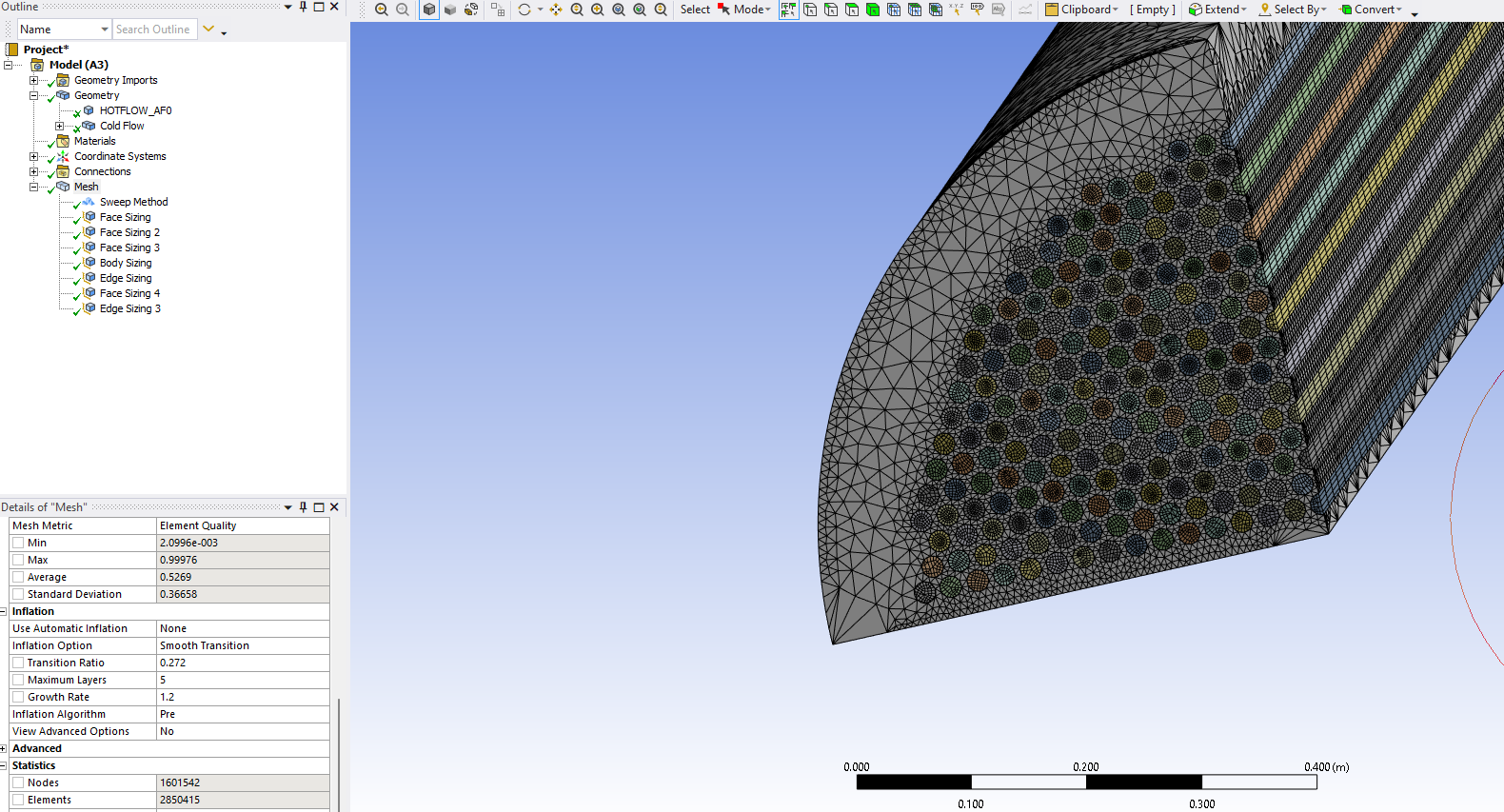
I am currently trying to mesh a shell and tube heat exchnger with 786 tubes but have quartered the geometry so am able to run the sim using the student license. I need some help meshing as at the moment I am just trying to get an initial course mesh but am having trouble getting the node count down enough to be able to run it. When first meshing it was going upwards of 50 mil nodes but I have got it down to 1.6 mil. I just would like to know how I should be meshing it, I have used a sweep for the tubes (cold flow) and have been using body sizing and face sizing for the hot flow region. I have noticed that on the sides I have tried to get the sizing down where there is plenty of space for bigger elements, it has kept the element size small for some reason which is giving me too many nodes.
I am fairly new to having to "manually" mesh in fluent so any help would be appreciated and lmk if any more info is needed.
-
July 22, 2024 at 7:29 am
-
July 22, 2024 at 7:40 am
-
July 22, 2024 at 12:51 pm
Rob
Forum ModeratorYou've got a few problems here.
Each tube needs mesh resolution across it, but if you stretch swept mesh as we would for a pipe the high aspect ratio cell on the wall will cause problems with the tet region in the shell side. The cell count on the tubes is also going to be fairly high.
There are ways around this if you look into domain decomposition. It's an older technique that can come in very useful for this situation.
Another option: do you really need to model tubeside? What is the purpose of the simulation?
-
July 23, 2024 at 10:38 am
joel.sayers
SubscriberThank you Rob for the reply. I will make sure to look into domain decomposition thank you. This is just an initial simulation of the heat exchanger without baffles for simplicity, but the purpose of it is to test results with disc and doughnut baffles eventually to verify results that were obtained through different software. Are you suggesting that I could perform the simulation without the tubes, especially if the heat trasnfer coefficient between the two sides is known? This may be suitable due to the purpose of the simulation but I would rather atleast try and find a way for it to run first.
-
-
July 23, 2024 at 10:52 am
Rob
Forum ModeratorOmitting tubeside is a sensible option if you're just wanting to compare baffle configurations. You'd need to add heat from those walls, but running many domains will cost you a lot in terms of cell count so it's probably a good idea given the cell count limits of Student. Make sure you read up on the various HTC options from Fluent's output; you may find comparing temperature and heat flux to be more useful.
-
July 25, 2024 at 2:57 am
joel.sayers
SubscriberOkay I get you, so adding this heat is done in the setup after meshing I'm guessing. I have most of these parameters so that should be sweet. Thank you very much for the help, do you have any suggestions on the best way to mesh that shellside?
-
-
July 25, 2024 at 3:41 pm
Rob
Forum ModeratorHeat etc are boundary conditions so done in the Fluent Solver.
Decompose the shell side. Can you alter the geometry to sweep more of it? Remember a fluid region can comprise many CAD/mesh level volumes.
-
- The topic ‘Meshing Shell and Tube Heat Exchanger’ is closed to new replies.


-
4597
-
1495
-
1386
-
1209
-
1021

© 2025 Copyright ANSYS, Inc. All rights reserved.

.png)

.png)
.png)


