-
-
March 26, 2024 at 6:01 pm
-
March 27, 2024 at 8:36 am
Prashanth
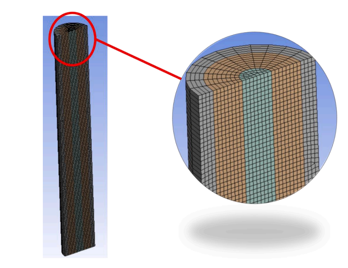
Ansys EmployeeHello, we use 'edge sizing' for the suitable edges to make the mesh look like that.
-
March 27, 2024 at 3:55 pm
omar.ennaya
Subscriberhi Prashanth
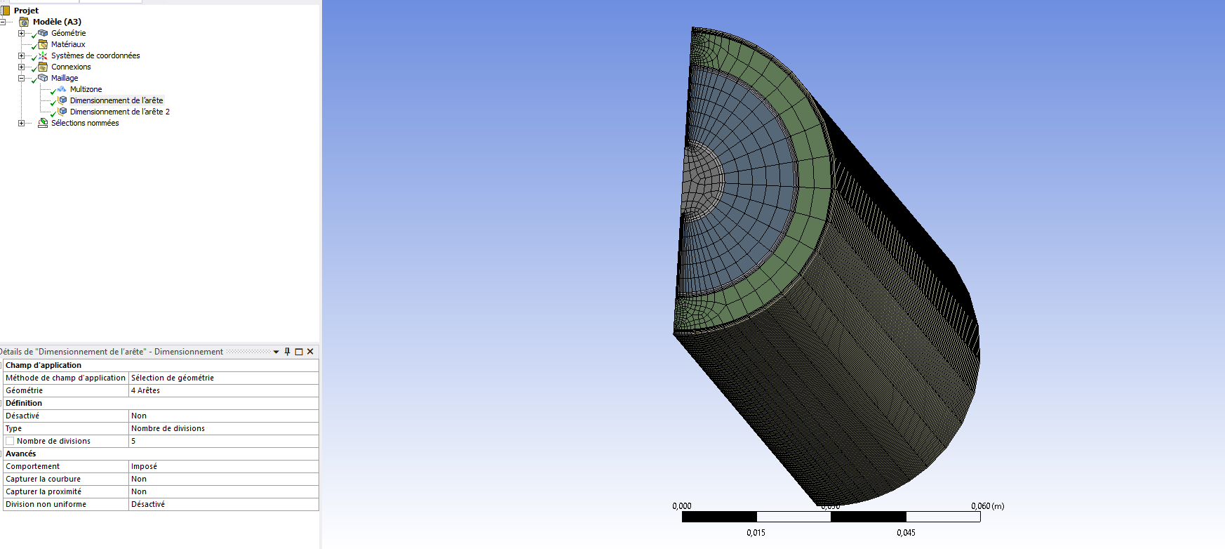
i used the edge sizing but look at the boundaries at the centre of the cylindre are not structured as in the middle.
thank you for your feedback.
-
March 28, 2024 at 9:32 am
NickFL
SubscriberTry using the Face Meshing (mapped) for the C faces. It could be you have a global size which it is defaulting and only putting the sizing on the edges.
-
-
-
Viewing 1 reply thread
- The topic ‘meshing issues’ is closed to new replies.
Innovation Space


Trending discussions


Top Contributors


-
4628
-
1535
-
1386
-
1215
-
1021
Top Rated Tags


© 2025 Copyright ANSYS, Inc. All rights reserved.
Ansys does not support the usage of unauthorized Ansys software. Please visit www.ansys.com to obtain an official distribution.


