-
-
November 17, 2023 at 9:44 am
Elena Maier
SubscriberHello,
my problem is the following:
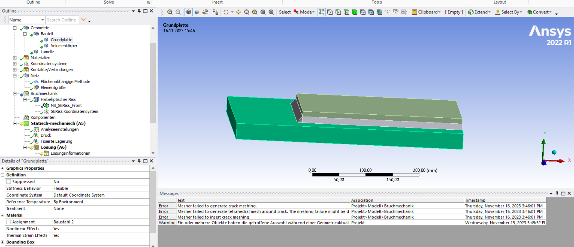
my model contains a plate and on top of this plate is a smaller plate (cover plate) welded. Also there is a crack in the beginning of the weld, as you can see:
The following boundary conditions are set;
- the welds (triangle volume bodys) and the bottom plate are one Part with a shared topology, since through the welding process they are one piece and that´s how the mesh gets continoous.
- the cover plate (upper plate) is bonded to the welds with an MPC, since they are also connected through the welding. The contact between the cover plate and the bottom plate is defined through friction (coefficient:0,2) because they are not bonded or something.
- the back is fixed and on the left side is a tension with 100 MPa (or a pressure with -100 MPa)
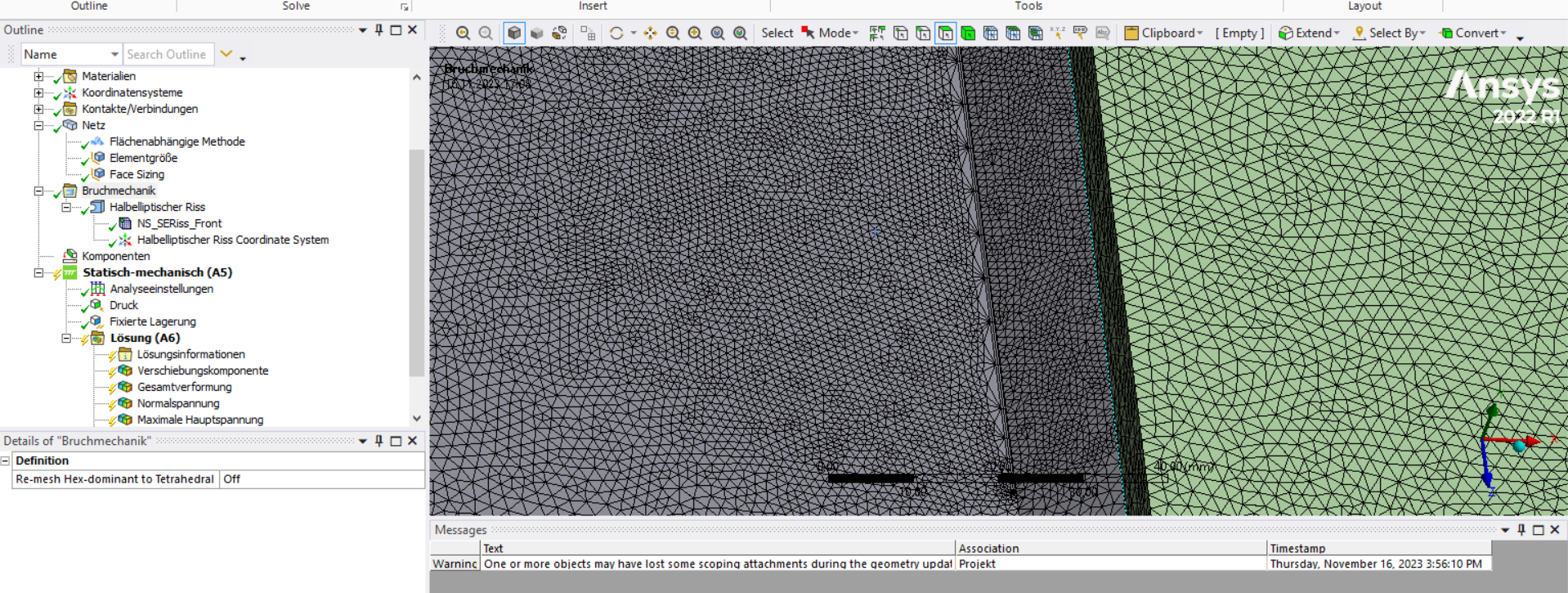
- on the weld toe is a semi elliptical crack which I inserted with the fracture Tool over semi elliptical crack, see also below:My problem is: I do a parameter study and sometimes the crack meshs with the surrounding mesh and sometimes not. I assume it is because it is difficult because it is so close to the weld toe.
1. Is there a way to get a stable meshing for all crack sizes?
2. My simulation takes very long with an element size of 2, is there a way to get it faster?
3. how close can I go to the weld toe? right now my closest is 0,3 mm (with a hexaeder mesh and a largest profile radius of 0,2mm )
Thank you so much for your time and help.
Best regards,
Elena -
November 17, 2023 at 1:59 pm
SHELL
Ansys EmployeeHello Elena,
Generally, please note that among the Fracture Meshing tools the Semi-elliptical Crack feature has more limitations than the Arbitrary Crack feature. E.g. the Semi-elliptical Crack feature can only be applied to one surface/face and only remeshes there. That will make it difficult to achieve a crack mesh close to the border of a face.
https://ansyshelp.ansys.com/account/secured?returnurl=/Views/Secured/corp/v232/en/wb_sim/ds_fracture_limits.htmlThe Arbitrary Crack feature on the other hand can cross faces as long as they belong to the same body. That might help you in achieving an appropriate mesh more often.
Note that the Fracture Meshing tools are intended for cracks within a bulk material where SIF results are actually valid (they are not in material interfaces). For interface cracking/debonding applications, you could use CZM or VCCT (https://ansyshelp.ansys.com/account/secured?returnurl=/Views/Secured/corp/v232/en/wb_sim/ds_geo_delam_debond.html).
I hope this information will help you.
Regards,
Sascha
-
November 17, 2023 at 4:09 pm
Elena Maier
SubscriberHello,
thank you so much. I can´t open the links, that doesn´t work.
I got that a little to late, I am already really far in my validation process and it is difficult to do it now with a total different crack type. Because in the beginning I thougt it could work with that crack.
Is the rest of my meshing/ contact definition realistic/good like that?
And do you have an idea how I can mesh this, to get still ok results?
It would help me a lot, thanks for your answer in advance,
Best regards
Elena-
November 20, 2023 at 8:35 am
SHELL
Ansys EmployeeHello Elena,
the links are links to the Ansys Help. Don't you have access to the Ansys Help?
Unfortunately, I cannot comment on your engineering approach, so I cannot help you in deciding whether your meshing/contact definition is appropriate. Hopefully, someone else can comment on that.
What I can say is: If you want to reliably get a mesh using the Semi-Elliptical Crack feature, you should stay well away from the surface/face boundaries (that includes any contact and shared topology definitions). The same is true to get appropriate results for your contour integral evaluation. For the latter, the solver will help you by throwing a warning if there could be a potential issue.
Best regards and good luck for your application,
Sascha
-
-
November 20, 2023 at 3:13 pm
Elena Maier
SubscriberOk, thank you, no unfortunately that doesn´t work for me, because my institution is really big and they can´t give me the license number which it seems I need to get to ansyshelp.
Ok thank you for the information.
My colleague is working with the arbitraty crack, and it seems less stable than the semi elliptical crack. thats why I chose that one, and in the beginning I was distant from the other body, but now I have to model the crack closer.
-
- The topic ‘Meshing around a semi elliptical crack; warning: during crack meshing error’ is closed to new replies.


-
4823
-
1587
-
1386
-
1242
-
1021

© 2026 Copyright ANSYS, Inc. All rights reserved.


