-
-
May 1, 2022 at 6:23 pm
ragnhildurkristinsd
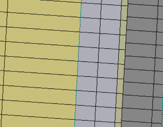
SubscriberIm analyzing a 1/4 3D geothermal well with 5 bodies. Im having trouble meshing it. Im using "edge sizing" and all the element align at the top of the well but when I go down, the element starts to not align, see picture below. Why is this happening?? is there a way to make the elements all by inline automatic?
May 3, 2022 at 1:58 pmSubscriber
Can you please help me mesh the corners in the 3D well? I tried slicing the body but I was unsuccessful. I also tried the mesh the point in the corner of two bodies
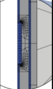
Im trying to achieve the mesh that is shown the picture below
here is my model:
https://drive.google.com/drive/folders/1sm7kLpGLBuQFx6wqIVr9_VCLVfJTEVCC?usp=sharing
May 4, 2022 at 8:12 pmpeteroznewman
Bbp_participantIn your model, Bonded Contact is used to connect the mesh across the bodies.
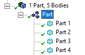
Use Shared Topology to get the mesh to line up across the five bodies. In DM, that is selecting the 5 Parts and Form New Part.
 However, when I mesh this, there is a small error in the geometry. If you turn on Close Vertices, you can see the four yellow highlights.
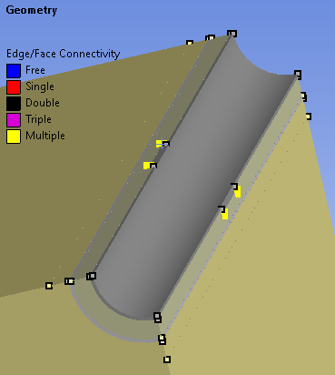 Please edit the geometry to eliminate this error.
 It will help with meshing if you split the bodies into more pieces.
In the SS Thermal model, one entire body has a constant temperature.
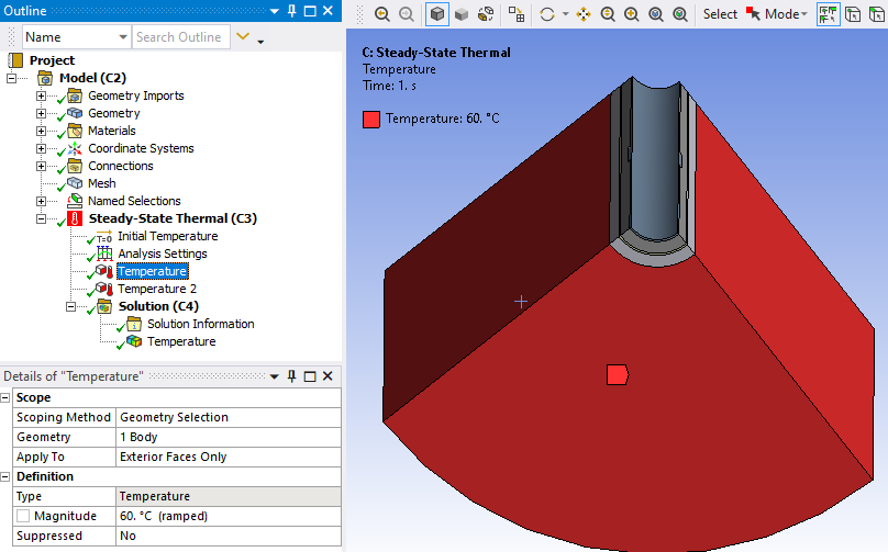 You could suppress this body and simply apply that temperature to the outside surface of the part it touches.
May 6, 2022 at 11:34 amSubscriberthank you, I fixed the geometry
"It will help with meshing if you split the bodies into more pieces"
How can I split the bodies, can I split the pipes in the middle so I can focus my mesh there?
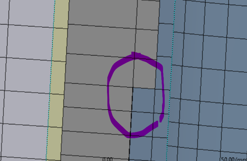
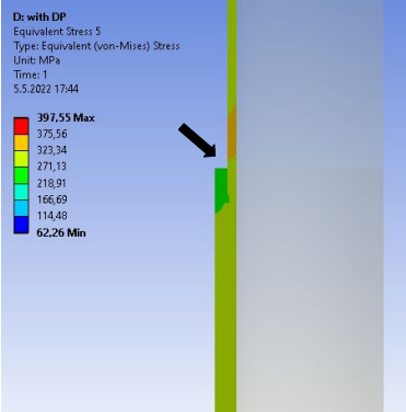
I want to take a look at the stresses where the couplings outside of the production casing are, and what effect the couplings are having on the production casing. Ansys only allows me to select the whole body or faces in the production casing and the highest stresses in the casing are on the bottom and top because of my boundary conditions and I have an interest in those results, I want to take a closer look at what happens where the couplings are on the production casing.
In In the picture below the highest stress is 397.55 which is located at the top of the casing, I want to take a look at what is happening in the casing where the arrow points
May 6, 2022 at 11:41 amBbp_participantOpen the geometry in SpaceClaim. Use the Split Body button and split all the bodies at the plane of the coupling edges. Use the Split Body button to split the stepped diameter off the base diameter. On the Workbench tab, use the Share button to make the mesh share nodes on the coincident faces.
Viewing 4 reply threads- The topic ‘meshing a sharp corner’ is closed to new replies.
Ansys Innovation Space Trending discussions
 Top Contributors
-
peteroznewman
 421
421 -
javat33489
 192
192 -
1617836513
 178
178 -
zzhang868
 162
162 -
Saeed
140
Top Rated Tags
© 2024 Copyright ANSYS, Inc. All rights reserved.
Ansys does not support the usage of unauthorized Ansys software. Please visit www.ansys.com to obtain an official distribution.
-