TAGGED: gear, spur-gear, transient-structural
-
-
February 17, 2023 at 11:15 am
Clarkt
Subscriber -
February 17, 2023 at 5:56 pm
peteroznewman
SubscriberWhy do you say "for this study I will need to use transient structural"?
Other than a brief period when the frictional force transitions from sticking to slipping, it is essentially a statics problem with no significant inertial forces. You are using very low velocities.
If the static friction and dynamic friction are the same value, then there is no release of strain energy when the slipping begins so no significant inertial forces develop.
I suggest you use a Static Structural model. Both gears have a Revolute Joint to Ground on the hole ID. One gear has a Joint Load of Rotation, the other gear has a Joint Load of Moment.
A multistep analysis is used. In step 1, the Rotation is set to 0, holding that gear fixed, and the Moment is ramped up to the 40 Nm torque. At some point in step 1, the contact goes from sticking to slipping.
In step 2, a small rotation is ramped on. Sliding continues and the contact point moves up or down the tooth, depending on which tooth you are looking at.
-
February 18, 2023 at 10:57 pm
Clarkt
SubscriberThank you for your reply!
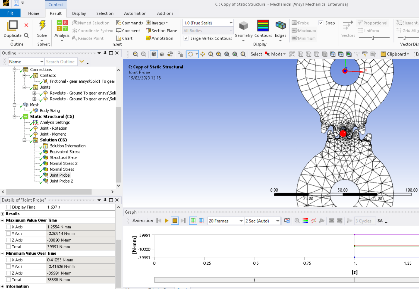
I think I have followed your instructions precisely. The simulation has run, but I how exactly can I probe/calculate the pretension torque I am looking for and which causes the gears to require such a high moment to move that little?
-
February 18, 2023 at 11:04 pm
peteroznewman
SubscriberOne gear has a moment load, the other gear rotates to move that load. You can Probe the Reaction Moment on the Joint that has the rotational input. If you put 40 Nm as a torque load on one gear, the driving gear with the rotational input will probe with a higher value. The size of the torque depends on the shape of the gear tooth and the coefficient of friction you assigned to the contact.
-
February 19, 2023 at 10:20 am
-
February 21, 2023 at 6:45 pm
peteroznewman
SubscriberWhat direction is the rotation of the driven gear? Is it advancing against the moment on the other gear or is it retreating from the moment on the other gear? Those two directions of rotation will have a different reaction moment if there is a significant friction on the tooth contact. If the contact is frictionless, then the moment will be the same in each direction.
-
February 22, 2023 at 1:42 pm
Clarkt
SubscriberThank you for your time. It is advancing against the moment. I 've experimented with many configurations, but I haven't managed to get the pretension moment to show up. All I am getting is 40 Nm and I reckon it is quite impossible for the pretension to coincide with the external moment.
Here are there settings of the frictional contact:
-
February 22, 2023 at 7:05 pm
peteroznewman
SubscriberI just remembered something about involute gear teeth profiles. Ideally, they don't slide, they roll on each other. That means the friction would not change the answer and the correct output torque is identical to the load of 40 Nm.
Now if you have a non-involute tooth face (a bad idea) then you will get sliding at the contact point and then the direction of rotation will make a difference.
-
- The topic ‘’ is closed to new replies.


- LPBF Simulation of dissimilar materials in ANSYS mechanical (Thermal Transient)
- Real Life Example of a non-symmetric eigenvalue problem
- How can the results of Pressures and Motions for all elements be obtained?
- BackGround Color
- Contact stiffness too big
- Element Birth and Death
- Python-Script to Export all Children of a Solution Tree

-
4597
-
1495
-
1386
-
1209
-
1021

© 2025 Copyright ANSYS, Inc. All rights reserved.


