We’re putting the final touches on our new badges platform. Badge issuance remains temporarily paused, but all completions are being recorded and will be fulfilled once the platform is live. Thank you for your patience.
Fluids

Fluids

Topics related to Fluent, CFX, Turbogrid and more.

Mesh Study Vortex Induced Vibration Problem

    • marco.pedata
      Subscriber

      Hello ANSYS community,

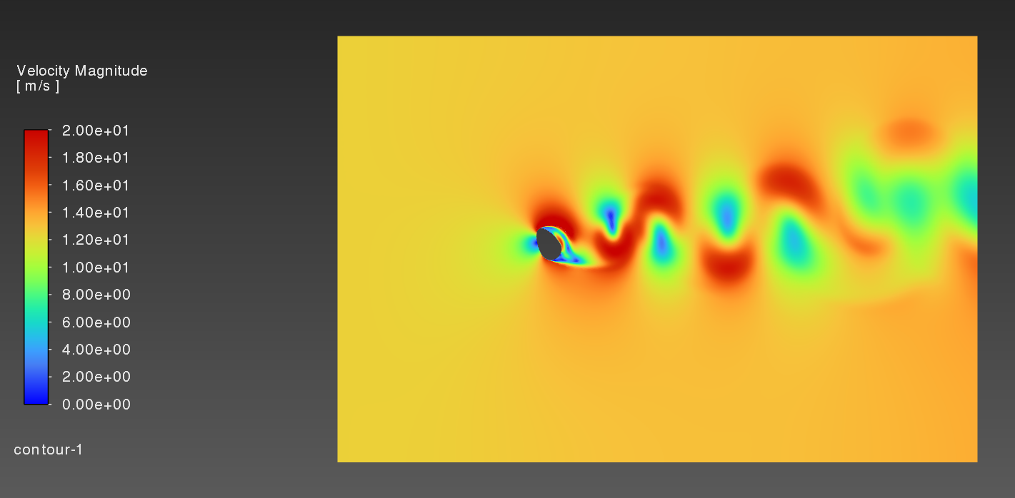
      I try to perform a mesh convergence study on a problem similar to that of a flow around a cylinder. The problem is transient and I use the SST-k-omega model.

      I use 12 inflation layers around my cylinder wall and an unstructered tiangular mesh for the rest. I started with a time step of dt=1e-4 and determined the element of the triangular mesh via CFL=1 even though the simulation is implicit. For the inflation layers I calculated the element size via y+ from boundary layer theory. I am interested in the vibration frequency due to lift forces. Therefore, I performed a FFT for each simulation and looked at the frequency. I tested y+ = 1 -> f = 140 Hz, y+ = 2 -> f = 130 Hz, y+ = 0.5 -> f = 140 Hz. I settled for y+ = 1. Than I tested different time steps: dt = 1e-4 -> f = 140 Hz, 1e-3 -> f = 99 Hz, 1e-5 -> f = 120 Hz. The frequency did not converge for smaller time steps. I simulated a timespan of 0.1 s. Maybe I need to run the simulation for longer time period? What are your thoughts on this. Do I approach the mesh study correctly or should I try a different approach? I attached a figure showing the Cl coefficient over time. Please note that in this figure the simulation for the smallest time step is not yet finished as the system corrupted and I needed to restart the simulation. However the result for 0.1 s was 120 Hz.

      As this is my first CFD simulation I welcome any tips and advice on how to proceed :)

    • Rob
      Forum Moderator

      It's possible you've not run for long enough. Is it the same flow with just the time step decreasing? If you also plot contours of velocity or similar how's that looking? 

    • marco.pedata
      Subscriber

      Thank you! 

      I will try to run the simulation for longer time periods. Qualitively speaking the velocity contour plots look similar for dt = 1e-4 and dt = 1e-5. 


    • Rob
      Forum Moderator

      You may be picking up a fast transient somewhere too. 

    • marco.pedata
      Subscriber

      Okay I will keep that in mind. As this is a transient problem I need to run it long enough to get good results. How can I determine what long enough is? I suppose that this simulation time depends on the initialization. I used Standard Initialization and speceified a constant flow field computed from the inlet. Would hybrid initialization reduce the simulation time needed?
      Can I utilize the residuals plot in some way to determine at what time the results may be of good quality? 

    • Rob
      Forum Moderator

      Residuals are good for checking convergence on each time step; monitors are for checking whether the solution has reached the equilibrium transient condition. 

Viewing 5 reply threads
  • You must be logged in to reply to this topic.