TAGGED: -Structured-Meshing, hexa-mesh, mesh
-
-
December 12, 2022 at 10:26 pm
Yaniv Ben David
SubscriberHi,
When I create a revolved geomatry (via SpaceClaim or other CAD software) and then try to mesh it in the structural analysis module - I find it quite challanging to create an HEX mesh.
Changing the mesh size, using the hex dominant or MultiZone methods - all feel like a voodoo. It may become successful sometimes, but sometime all I get is tetra mesh.
Is there a way to "tell" the software that there is a constant cross section that was revolved along a specific axis? Is there any other way that can improve the chances for a good hex mesh in this case? -
December 13, 2022 at 12:43 am
peteroznewman
SubscriberIf the geometry is purely a revolved feature, and the loads are axisymmetric, then you should create an axisymmetric model and only mesh the surfaces on a radial slice in the X-Y plane where Y is the axis of revolution.
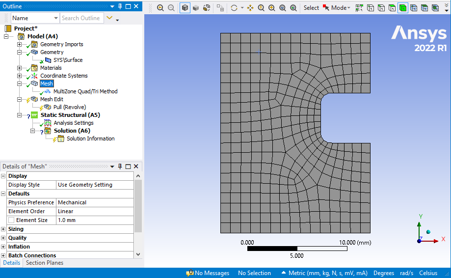
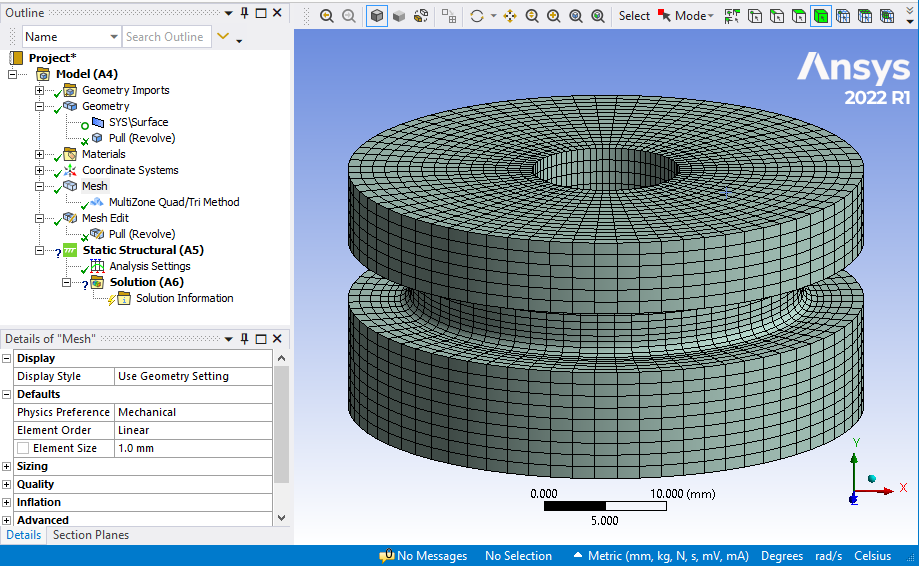
If you need to apply loads in 3D, then you can still bring in just the radial slice, but use the Pull feature to revolve the 2D mesh around the axis. Here is the 2D mesh:
Here is the 3D mesh after using the Pull feature.
-
December 13, 2022 at 10:04 am
Erik Kostson
Ansys EmployeeHi
If it is really axisymmetric (about a global axis) then it could be possible to sweep mesh (Method), using the axisymmetric algorithm (choose this option in the Sweep Method definition and under Algorithm setting -> choose Axisymmetric )
All the best
Erik
-
December 13, 2022 at 10:22 am
Rahul Kumbhar
Ansys EmployeeIf it is revolved geometry, you can slice in two 180 degree sections and use 'Sweep mesh method'
-
December 13, 2022 at 6:46 pm
Yaniv Ben David
SubscriberThank you all guys.
What do I do in case this geomatery is a part of assembly. The mating parts or not revolved features and there should be specific connetions between them?
Or in a case the feature is almost purely revolved, but has several holes (for instance) that break this definition?
In these cases, starting from a surface and revolve the mesh, or slicing the geomatry may not be helpful. I think what Erik suggested is closest to what I imagined - should the revolve axis be located excectly on the global coordinate system? -
December 13, 2022 at 7:30 pm
peteroznewman
SubscriberIf there are holes in the part that break the axisymmetry, then you can’t use these sweep methods without splitting the body up into sweepable pieces. It may help hex meshing to use a plane to split the body through the center of the hole.
-
- The topic ‘Mesh for revolved geometry’ is closed to new replies.


-
2337
-
925
-
599
-
591
-
527

© 2025 Copyright ANSYS, Inc. All rights reserved.


