TAGGED: mesh-convergence
-
-
June 2, 2024 at 10:58 am
sgkcompany
SubscriberHi I'm doing mesh convergence in my model
When I apply more mesh in my model the important node's stress get lower and than increase a little
Normally it should get higher right?
x axis is mesh count, y axis is von mises stress
blue line is max von mises stress
orange line is important node's in average von mises stress
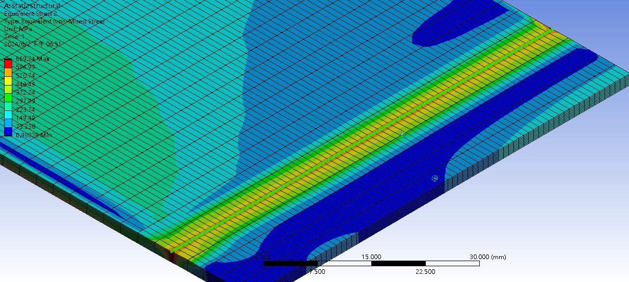
This line is where I think is important node's location, because it's where roller press the plate in last moment.
I get all node on this line and average it.
Is it wrong to get this location's node or mesh problem (the way generate mesh is wrong)?
my model
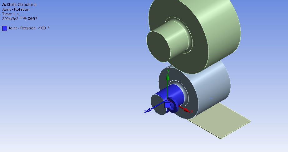
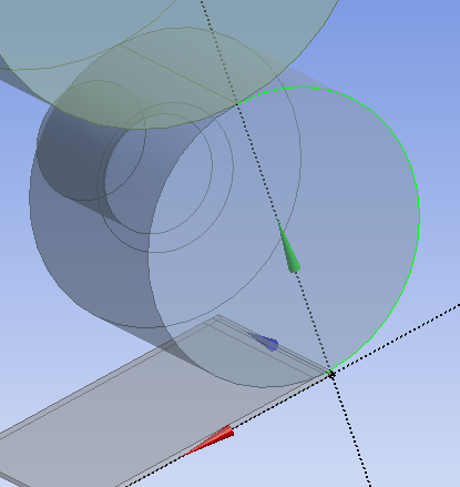
the only boundary condition I gave -
June 4, 2024 at 8:00 am
Kaushal Vadnere
Ansys EmployeeHi Patrick,
The stress value should rise with mesh refinement in case stress singularities are present. In the graph you shared, it is showing that the maximum stress values remain fairly consistent with increasing mesh count indicating absence of singularities.
In case where the mesh is coarse, bad elements can get highly distorted with large deformation and result in higher stress values. Mesh refinement in this region can lead to better element quality and hence, better stress distribution (This may result in lowering of stress values as well).
To answer your other question regarding the wrong mesh genration, by looking at the mesh, it seems there are no generation issues.
Before coming to any conclusion, I would want to know few more things:
What is the use of the upper roller (bigger one)? because you have mentioned that you are applying joint-rotation to only the bottom roller. is there any contact defined between the bottom and upper roller?
In the 2nd screenshot (Equivalent Von-Mises Stress) is display set to auto scale (>1x) or True Scale (1x) ? If it is at true scale, the element aspect ratios seems unreasonably high. By that I mean, the hex elements look more like a plate rather than cube which is an ideal shape of hex elements.
Also, you have used 7 elements through the thickness, is there any specific reason for that? if not, this will result in high element aspect ratios as mentioned above and un-neccessarily increase mesh count and solution time. I would suggest to go with 3-4 layers and try to keep aspect ratio close to 1 (This means keeping the length, width and depth of the element same). You can define element size = length of smallest edge/3 or use edge sizing in mesh to define no. of divisions for each edge.
What contact settings are you using?
Which support are you using and where? My assumption is that you have applied fixed support to the botton of the plate -
June 4, 2024 at 12:29 pm
sgkcompany
SubscriberThank you for explainatinon, I never thought about high element aspect ratios can cause this problem.
I have to try how different shape of upper roller affect plate's deformation, upper roller doesn't ratate but I give it revolute joint so only rotate in z axis.
Yes all contact use normal lagrange, strange enough when I use augmented lagrange it seems harder to convergence even use 0.01 stiffness factor than normal one.
And plate usually move opposite direction (instead roll in, it move back).
It is true scale, thank you to indicate that, I will improve my element.
I use symmetry to cut the model xy plane and xz plane.
The plate touch the roller in begining.
No other condition applied.
auto substep off use 500, large deflection on.

-
June 4, 2024 at 1:17 pm
Kaushal Vadnere
Ansys EmployeeSo, from what I understand, the upper roller does not play any significant role in rolling of the the plate. so you can maybe suppress that to save the solution time.
The reason your plate goes in backwards direction is because you've not constrained it. You need to add a support (possibly a fixed support at the bottom of the plate). Refer to this free Anys Course on how to appropriately select boundary condition to match real life scenario: Structural Boundary Conditions | Ansys Innovation Courses
For Contacts, try using augmented lagrange with asymmetric behaviour and contact detection method "Nodal-Projected Normal from Contact". Make sure you have scoped the roller as contact side and plate as target. Also, try to keep element size for contact and target similar (you can define local element sizing on the roller surface). Refer to these free Ansys Innovation Courses to learn more about best practices in contacts: Fundamental Topics in Contact | Ansys Innovation Courses, Rigid Body Motion in Contact | Ansys Innovation Courses. -
June 4, 2024 at 10:03 pm
-
June 5, 2024 at 8:22 am
Kaushal Vadnere
Ansys EmployeeYou can repair split edges in Ansys Discovery. Refer to this article in Ansys Help for detailed steps: Consolidating Split Edges (ansys.com)
-
- The topic ‘Mesh convergence more mesh get lower stress’ is closed to new replies.


-
4678
-
1565
-
1386
-
1241
-
1021

© 2025 Copyright ANSYS, Inc. All rights reserved.


