Hi,
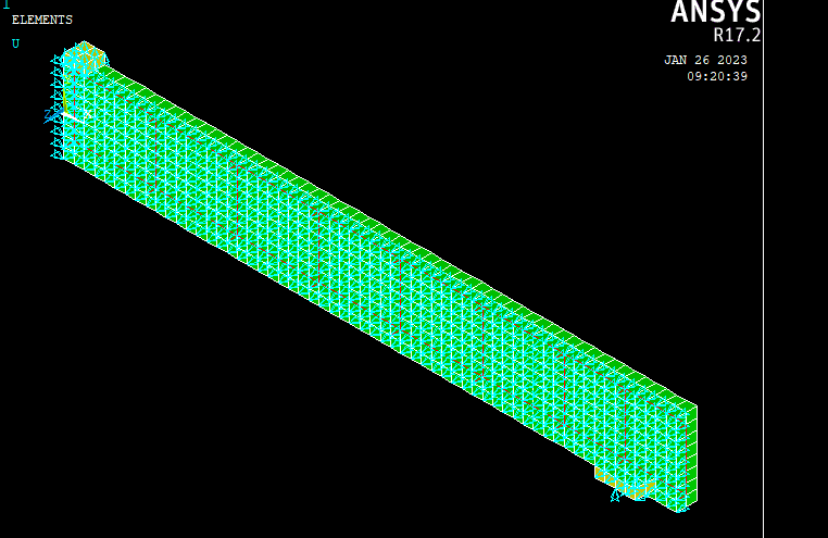
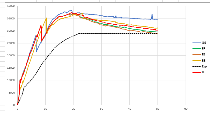
I've carried out a simple model of a static monotonically loaded reinforced concrete beam using a script. The model runs successfully, however it appears the load carrying capacity of the beam is excessively high, when compared with the experiment. For context, the experimental beam failed at 29kN & 50mm displacement. I have modelled one quarter of the beam due to double symmetry.
My script uses the legacy solid65, link180 (rebar) and solid 45 (steel support/loading plates). It also utilises the CONCR model, with crack shear coefficients of 0.1 & 0.4 for open & closed cracks, respectively. The script also uses the MELAS curve for the concrete. I've also played around with the stress-strain curve for the concrete, using a idealised curve that stops at the ultimate compressive strength. Use of a full curve with the descending branch makes the model fail prematurely (around 18mm) before the reaction loads turn to a negative value i.e. fail.
I've attached the script here and wondered if there was anything blatently obvious error wise? I've double & triple checked various parameters...
Even with use of the idealised stress-strain curve, my highest load is around 8-10kN too high, with the load-displacement curves being quite far apart.
The script is as follows:
! B Lovell
! December 2022
! RC Beam - Hughes & Speirs 1982
! RC Beam Run
!
!
fini
/prep7
/title,Hughes & Speirs RC Beam Analysis
!!! ELEMENT TYPES !!!
!
ET,1,SOLID65
!*
KEYOPT,1,1,0
KEYOPT,1,3,0
KEYOPT,1,5,1
KEYOPT,1,6,3
KEYOPT,1,7,1
KEYOPT,1,8,0
!*
!*
ET,2,LINK180
!*
KEYOPT,2,2,0
KEYOPT,2,10,0
!*
!*
ET,3,SOLID45
!*
!*
KEYOPT,3,1,0
KEYOPT,3,2,0
KEYOPT,3,4,0
KEYOPT,3,5,0
KEYOPT,3,6,0
!*
!*
!!! MATERIALS!!!
!
!
!Concrete
mp,dens,1,2400 !2400kg/m3 for concrete
mp,ex,1,3.431e+10 !Youngs modulus
mp,prxy,1,0.2 !Poissons Ratio
TB,CONCR,1,1,9,
TBDATA,,0.1,0.4,3.27e6,-1, !Concrete Non-metal plasticity model
TBDATA,5,,,,,0.6,
!
TB,MELAS,1,1,17, !Concrete multilinear elasticity model
TBTEMP,0
TBPT,,0,0
TBPT,,0.0005129,1.76E+007
TBPT,,0.0008,2.46E+07
TBPT,,0.001,2.93E+07
TBPT,,0.0012,3.35E+07
TBPT,,0.0014,3.70E+07
TBPT,,0.0016,3.98E+07
TBPT,,0.0018,4.19E+07
TBPT,,0.0020,4.33E+07
TBPT,,0.0022,4.40E+07
!
!
!Reinforcement
mp,dens,2,7850 !Density 7850kg/m3 for steel rebars
MP,EX,2,2.06E+011 !Youngs modulus
MP,PRXY,2,0.3 !Poissons Ratio
TB,MISO,2,1,4,0 ! 2 x 4 array
TBTEMP,0
TBPT,,0.0017864,3.68E+008
TBPT,,0.0042464,4.6E+008
TBPT,,0.15,5.6E+008
!
!
!Rigid steel plates for loading/support
mp,dens,3,7850 !Density 7850kg/m3 for steel plates
MP,EX,3,2.06E+011 !Youngs modulus
MP,PRXY,3,0.3 !Poissons Ratio
!
!
! Rigid Concrete element for support
mp,dens,4,2400 !2400kg/m3 for concrete
mp,ex,4,3.2e10 !Youngs modulus
mp,prxy,4,0.2 !Poissons Ratio
!
!
!
!
!
!!! ELEMENT REAL CONSTANTS !!!!
!
!
R,1,0, , , ,0, ,
!
R,2,1.13097e-4, , (For 12mm tension rebar)
!*
!
!R,2,5.02655e-5,, (For 8mm, thicker first shear link)
!
!*
R,3,2.82743e-5,, (For 6mm compression + remaining shear links)
!*
!*
!*
!!! COMPONENT VOLUMES METHOD !!!
!
!
BLOCK,0,0.2,-0.1,0.1,-0.05,0, ! Generate vol for concrete beam (200mm links)
BLOCK,0,0.2,-0.075,0.075,-0.025,0, ! Generate vol for rebar area (200mm links)
VGEN,6,ALL, , ,0.2, , , ,0 ! Mirror vols for 6 instances (for 200mm spacing links)
BLOCK,1.2,1.35,-0.1,0.1,-0.05,0, ! Generate vol for concrete beam (150mm links)
BLOCK,1.2,1.35,-0.075,0.075,-0.025,0, ! Generate vol for rebar area (200mm links)
BLOCK,1.35,1.5,-0.1,0.1,-0.05,0, ! Generate vol for concrete beam (150mm links)
BLOCK,1.35,1.5,-0.075,0.075,-0.025,0, ! Generate vol for rebar area (150mm links)
BLOCK,0,0.05,0.1,0.125,-0.05,0, ! Generate vol for loading pad
BLOCK,1.3,1.4,-0.125,-0.1,-0.05,0, ! Generate vol for support pad
VOVLAP,ALL ! Overlap/connect various volumes
!
VSEL,S,LOC,Y,-0.1,0.1 ! Assign S65 element, concrete mat, section 1 to outer volume
TYPE, 1
MAT, 1
REAL,
ESYS, 0
SECNUM,
!*
ESIZE,0.025,0, ! Mesh 25mm sizing
VSWEEP,ALL
!
!
VSEL,NONE,ALL
VSEL,S,LOC,Y,-0.125,-0.1 ! Assign S45 element, rigid conc mat, to bottom support plate
TYPE, 3 !solid45
MAT, 3 !rigid Steel plate
REAL,
ESYS, 0
!*
ESIZE,0.025,0, ! Mesh 25mm sizing
VSWEEP,ALL
!
!
VSEL,NONE,ALL
!
VSEL,S,LOC,Y,0.1,0.125 ! Assign S45 element, rigid steel mat, to top loading plate
TYPE, 3 ! Solid45
MAT, 3 ! Original code says concrete? error? changed to rigid steel plate?
REAL,
ESYS, 0
ESIZE,0.025,0,
VSWEEP,ALL
!
VSEL,NONE,ALL
LSEL,NONE,ALL
!
!
LSEL,S,LOC,Y,-0.075 ! Select lines that make up bottom tensile reinforcement (D12 bars)
LSEL,R,LOC,Z,-0.025
TYPE, 2 ! Apply LINK180 elem
MAT, 2 ! Apply rebar material
REAL, 2
ESYS, 0 ! Apply 12mm diameter section
LMESH,ALL
!
LSEL,NONE,ALL
!
LSEL,S,LOC,Y,0.075 ! Select lines that make up top compression reinforcement (D6 bars)
LSEL,R,LOC,Z,-0.025
TYPE, 2 ! Apply LINK180 elem
MAT, 2 ! Apply rebar mat
REAL, 3
ESYS, 0 ! Apply 6mm diameter section
LMESH,ALL
!
LSEL,NONE,ALL
LSEL,S,LOC,Z,-0.025 ! Select & mesh shear links
LSEL,U,LOC,Y,-0.075
LSEL,U,LOC,Y,0.075
LSEL,A,LOC,Z,-0.0125
LSEL,R,LOC,Y,-0.075,0.075
LSEL,U,LOC,X,0
TYPE, 2 ! Apply LINK180 elem
MAT, 2 ! Apply rebar mat
REAL, 3
ESYS, 0
LMESH,ALL
!
LSEL,NONE,ALL
!
LSEL,S,LOC,Z,-0.025 ! Change REAL constant of fit, thicker shear link to 4
LSEL,U,LOC,Y,-0.075
LSEL,U,LOC,Y,0.075
LSEL,A,LOC,Z,-0.0125
LSEL,R,LOC,Y,-0.075,0.075
LSEL,R,LOC,X,0
TYPE, 2
MAT, 2
REAL, 3
ESYS, 0
LMESH,ALL
!
!
/GRAPHICS,POWER
!*
/TYPE,1,0
/CPLANE,0
/SHADE,1,1
/HBC,1,0
/REPLOT
ALLSEL,ALL
VPLOT
!
!
!
!!! Constraints !!!
!
!
! LHS Loading Plate
!
ALLSEL,ALL
NSEL,S,LOC,Y,0.125
D,ALL, ,-0.05, , , ,UY, , , , , ! Apply Y Displacement to loading pad area nodes
!
! RHS Support Plate
ALLSEL,ALL ! Apply support constraints at RHS of beam along support plate
NSEL,S,LOC,X,1.35 ! Select centre-line of support
NSEL,R,LOC,Y,-0.125
D,ALL, , , , , ,UY, , , , , ! Restrain beam along 'Y' axis (Down)
!
! Symmetry condition on LHS face in X plane
ALLSEL,ALL ! Apply symmetry constraints along LHS side (where remainder of beam length would be)
NSEL,S,LOC,X,0 ! Select nodes on LHS of beam
NSEL,U,LOC,Y,0.125
D,ALL, , , , , ,UX, , , , , ! Restrain beam along 'X' axis (Across)
!
! Symmetry condition on front face in Z plane
ALLSEL,ALL ! Apply symmetry BC to nodes at 0 Z position (half-width of actual beam)
NSEL,R,LOC,Z,0
NSEL,U,LOC,Y,0.125
D,ALL, , , , , ,UZ, , , ,
!
ESEL,S,MAT,,1
CM,CM_conc,ELEM
/color,CM,GREE,CM_conc
ESEL,S,MAT,,3
CM,CM_plates,ELEM
/color,CM,YELL,CM_plates
ESEL,S,MAT,,2
CM,CM_rebar,ELEM
/color,CM,RED,CM_rebar
ALLSEL,ALL
ESEL,S,MAT,,4
CM,CM_stiffconc,ELEM
/color,CM,BLUE,CM_stiffconc
ALLSEL,ALL
EPLOT
!
!
!
!
!!! SOLUTION !!!
!
!
ALLSEL,ALL ! Select all
CNVTOL,F, ,0.05,0, , ! Apply convergance tolerance values for NL solution
!*
DELTIM,5e-004,5e-005,5e-004
!
!
ANTYPE,0
NSUBST,1000,100000,1000
AUTOTS,1
TIME,1.0000
OUTRES,ALL,ALL
Many thanks if anyone has the time to read - would be greatly appreciated.


