-
-
March 22, 2023 at 3:22 pm
drdmsthesis
SubscriberHi,
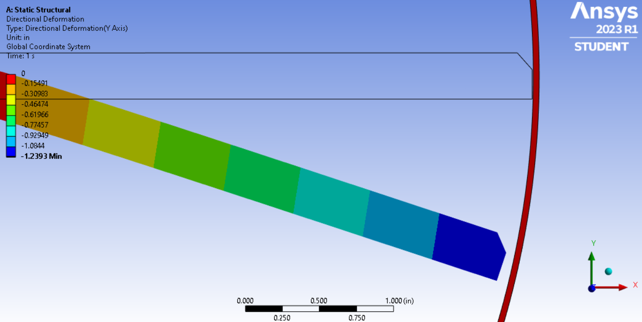
Is there a direct way to measure clearances between surfaces/distances between nodes? I could calculate using geometry, but it would have been convenient to post process the results directly in the workbench environment. The original clearances between rotor and shroud are 0.005".
The deflection plot lists the original gridpoint locations. Is there a way to show updated relative gridpoint distances?
Thank you.
-
March 23, 2023 at 4:48 pm
drdmsthesis
SubscriberFigured it out with a small post-APDL script.
Thank you.
-
March 23, 2023 at 5:33 pm
ErKo
Ansys EmployeeThat is great. If you do not mind since this might be useful to others, do you mind pasting the script into a post?
thank you
Erik
-
Viewing 2 reply threads
- The topic ‘Measuring Tip Clearances between Grid Points within Workbench’ is closed to new replies.
Innovation Space


Trending discussions


Top Contributors


-
4628
-
1535
-
1386
-
1215
-
1021
Top Rated Tags


© 2025 Copyright ANSYS, Inc. All rights reserved.
Ansys does not support the usage of unauthorized Ansys software. Please visit www.ansys.com to obtain an official distribution.


