
-
-
November 3, 2021 at 4:27 pm
idreeslisi6
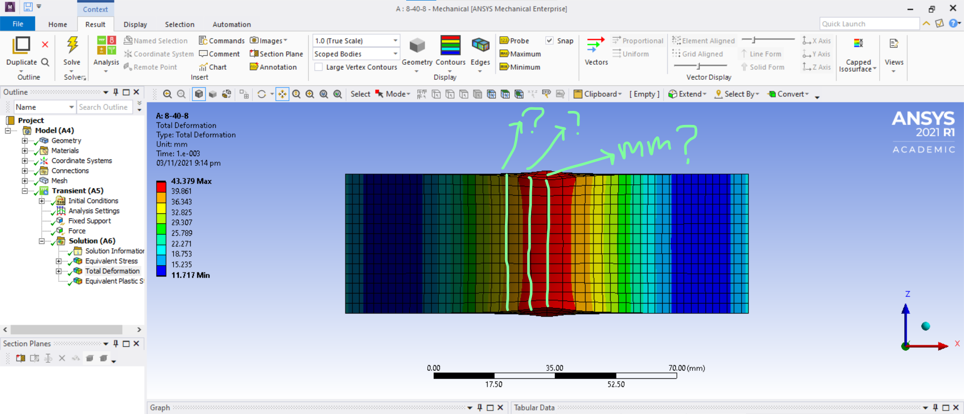
SubscriberPlease anyone could help me with this , i am really stuck here.In the pic bellow after bending a plate i wanna measure the width of the plate in the X-direction(wanna measure the distance of these 3 vertical lines) please anyone help me to do it in Ansys?
November 8, 2021 at 9:23 amSurya Prakash
Ansys Employee
As you mentioned that you require the distance in the x-direction, you might want to look at the directional deformation on the x-axis. To do that, right-click on Solution>insert>deformation>directional deformation and evaluate all results. Select probe in the Result ribbon on the top, and check the deformation at the two ends of the line that you want to measure.
Hope this helps.
Regards,
Surya
November 8, 2021 at 1:38 pmSubscriber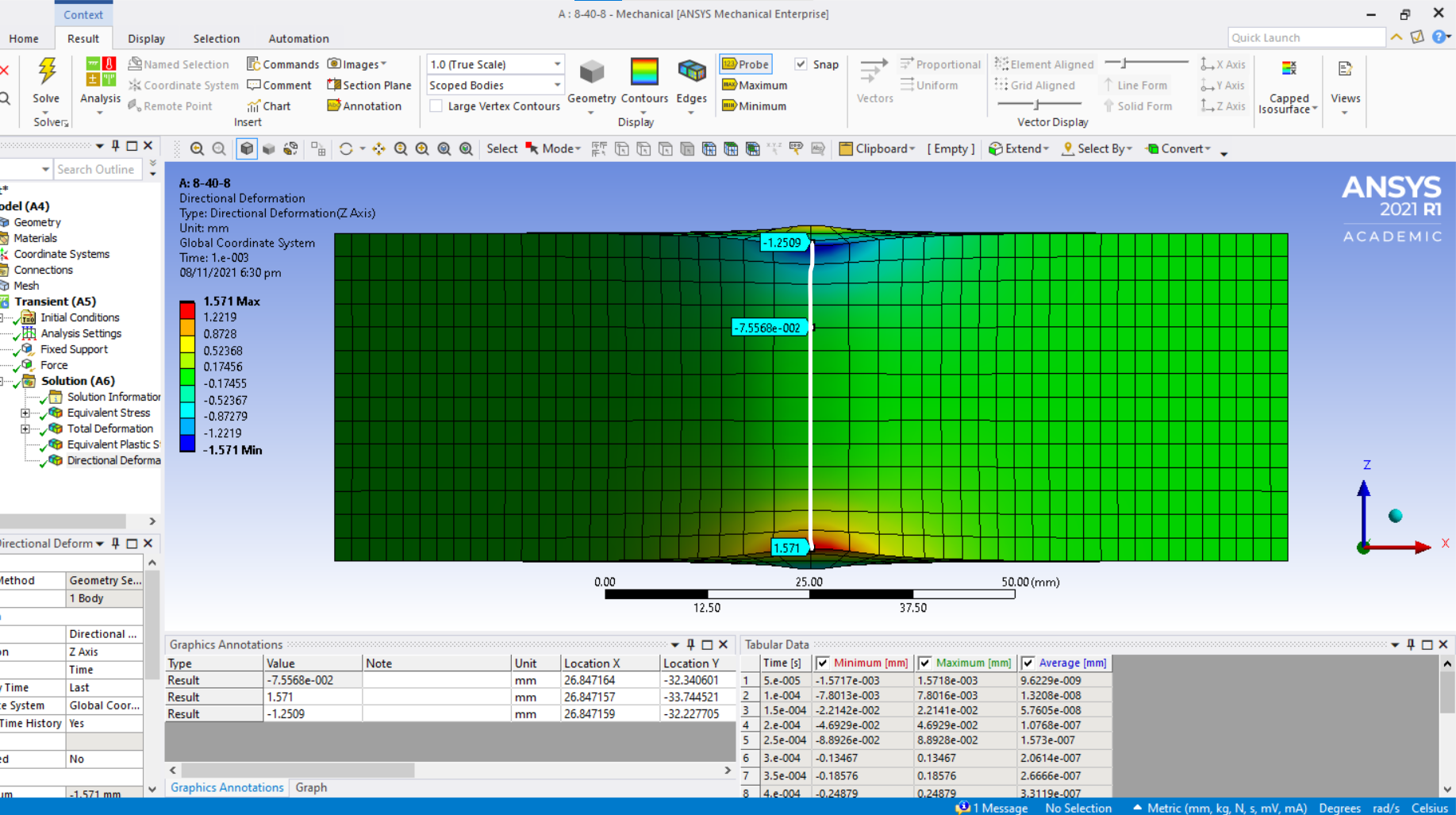 Sir i followed the steps you suggested me but when i probe i dont understand what it gives me.I just wanna know the distance of the vertical(white) line With the help of measuring node displacement.That is the width of the plate in Z-direction.To know how much the width of the outer layer of the plate is reduced after bending.
November 8, 2021 at 1:53 pmAnsys Employee
The directional deformation gives you the deformation value in that particular direction, rather than the total deformation. Since you have the deformation at the top node is -1.2509 mm ( -ve sign indicating deformation in negative z-direction), and at the bottom node is 1.571 mm, the total contraction will be 1.571 + 1.2509 = 2.8219 mm. This is the width of the outer layer that is reduced after bending. If you want the distance of the vertical line, then the total length before deformation - 2.82 mm gives you the value.
Hope this helps
Regards Surya
November 8, 2021 at 1:54 pmErKo
Ansys EmployeeHi
So the distance you could evaluate as follows.
Say the thickness of the part (z-dir) is 40 mm. Point on top goes down by - 1.25 mm, and the point at the base goes up 1.5 mm. Then the distance is
Dis = 40 mm - 1.25mm - 1.5mm ~37.25 mm
or thickness, 40 mm = 37.25+1.25+1.5
Hope this helps
Erik
November 8, 2021 at 2:28 pmSubscriber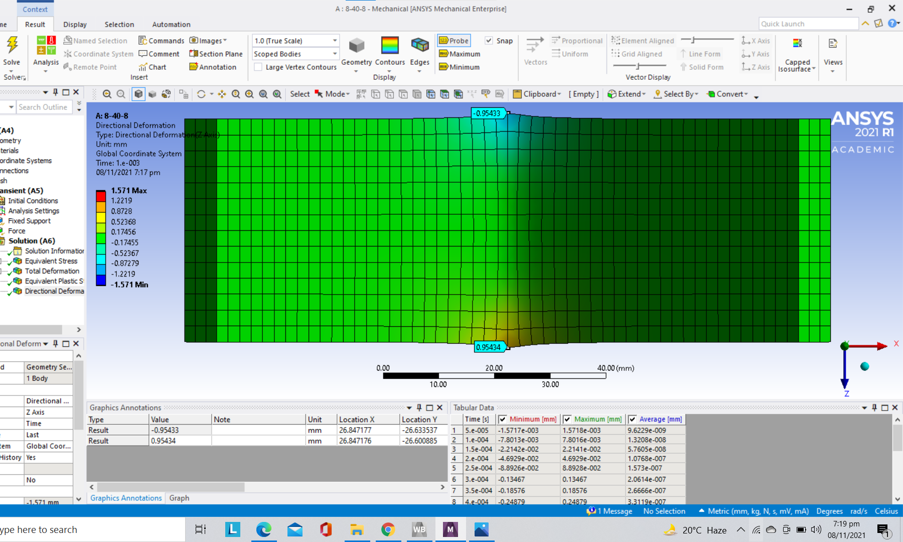 Sir this is the inner layer of the plate after bending.According t0 the bending nature the inner width of the plate should increase because of compression.The initial width of the plate is 40 mm.So according to your formula adding two nodes and then subtracat from the initial width is 0.95433+0.95433=1.908 , 40-1.908=38.092, which means the width is reducing in the inner layer as it is total contradiction against the bending nature. Please sir any suggestion to solve this confusing problem?
November 8, 2021 at 2:37 pmSubscriber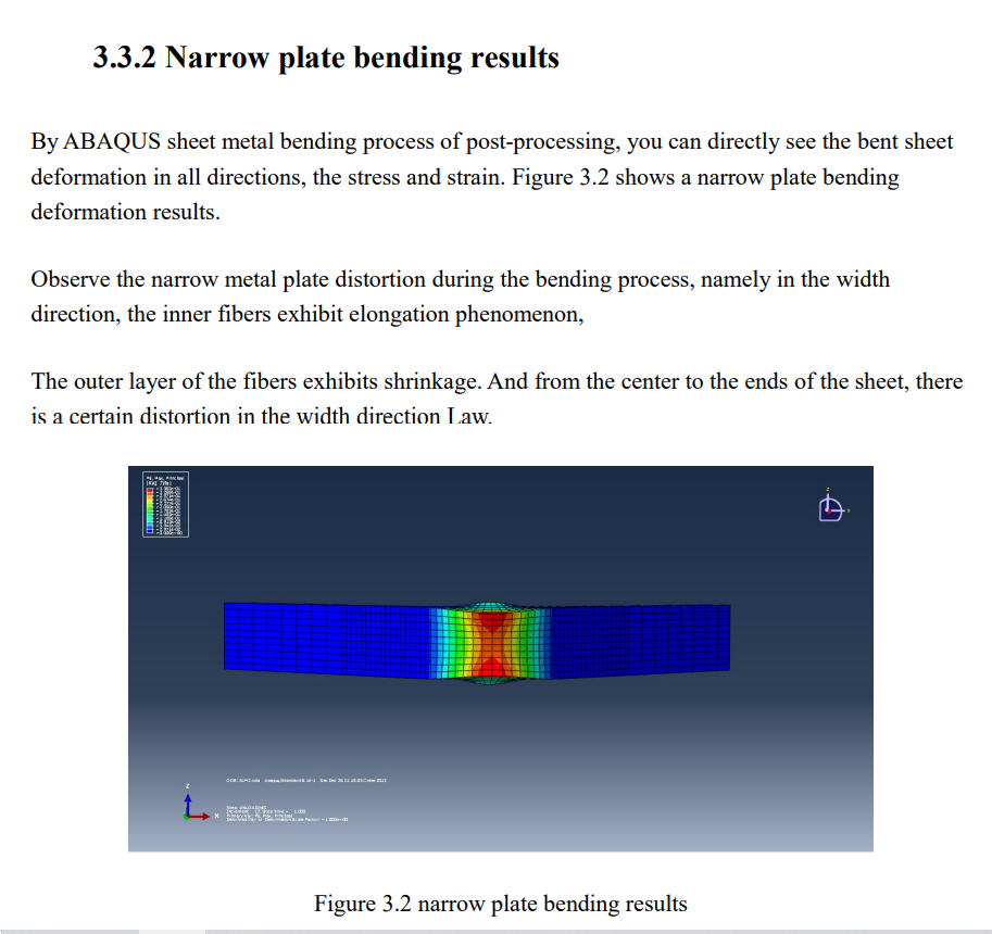
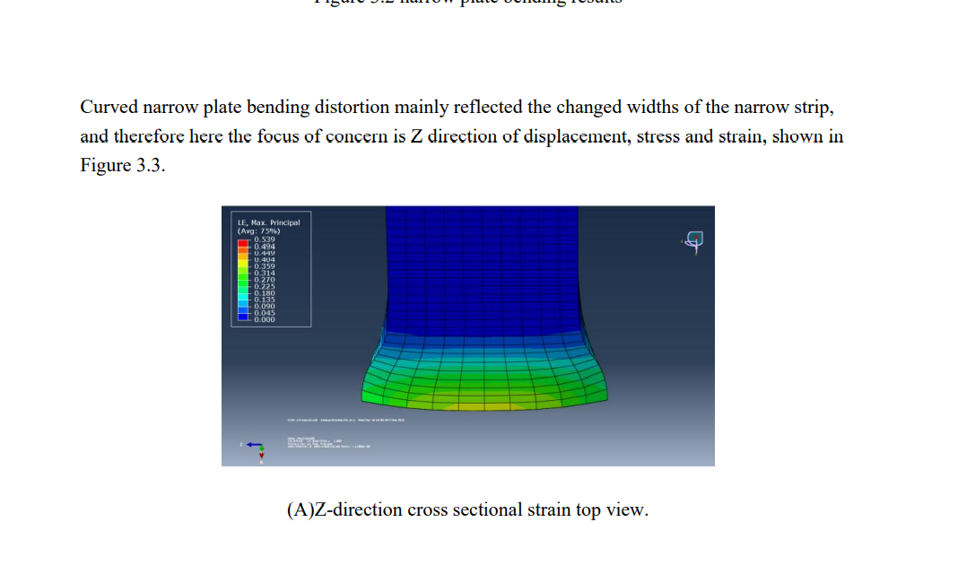
 Sir these are some refrence photos how they got width measurement at different layer.Devided the plate in 5 layers in thickness direction and measured the width at all the layers.It showed there is neutral layer E from it to outer layer width decrease and from it to inner layer width increase. In these pics the initial width was 10mm. They did this in Abaqus but i wanna perform the same in Ansys.
November 8, 2021 at 2:57 pmAnsys EmployeeHello
You said "So according to your formula adding two nodes and then subtract from the initial width is 0.95433+0.95433=1.908 , 40-1.908=38.092, which means the width is reducing in the inner layer as it is total contradiction against the bending nature. Please sir any suggestion to solve this confusing problem?"
have in mind that I just commented on the image you showed initially and just made a simple illustrative example so it is not an universal way for finding this, it is just a potential way, but needs thinking from the user - I hope you understand that.
In the image you showed now, you see that the distance is getting larger than the original width or height (I do not know what you look at but it does not matter if it is width or height) since they go up and down on respective side. So in this case, the distance is increasing than the actual original width/height so it is more like:
40mm + 2*0.95433mm ~ 41.9 mm.
So when one does this one must think how these points move relative the original width and subtract or add accordingly.
As for the other post I can not comment .
All the best
Eriik
November 10, 2021 at 7:24 pmSubscriberSir thank you so much for being so cooperative. Now have learnt how to measure the width distortion of the inner and outer layer but how can measure the width of any layer which is between the inner and outer layer? I mean I can suppose three more layers sandwich between the upper and lower surfaces(layers).
November 11, 2021 at 8:33 amAnsys Employee
We can create different section planes to see the distortion or any other results inside the part. I would suggest you look into this help documentation - Creating Section Planes (ansys.com)
Thank you Surya
November 13, 2021 at 4:10 amSubscriberOk Thank you sir!
November 13, 2021 at 4:23 amSubscriber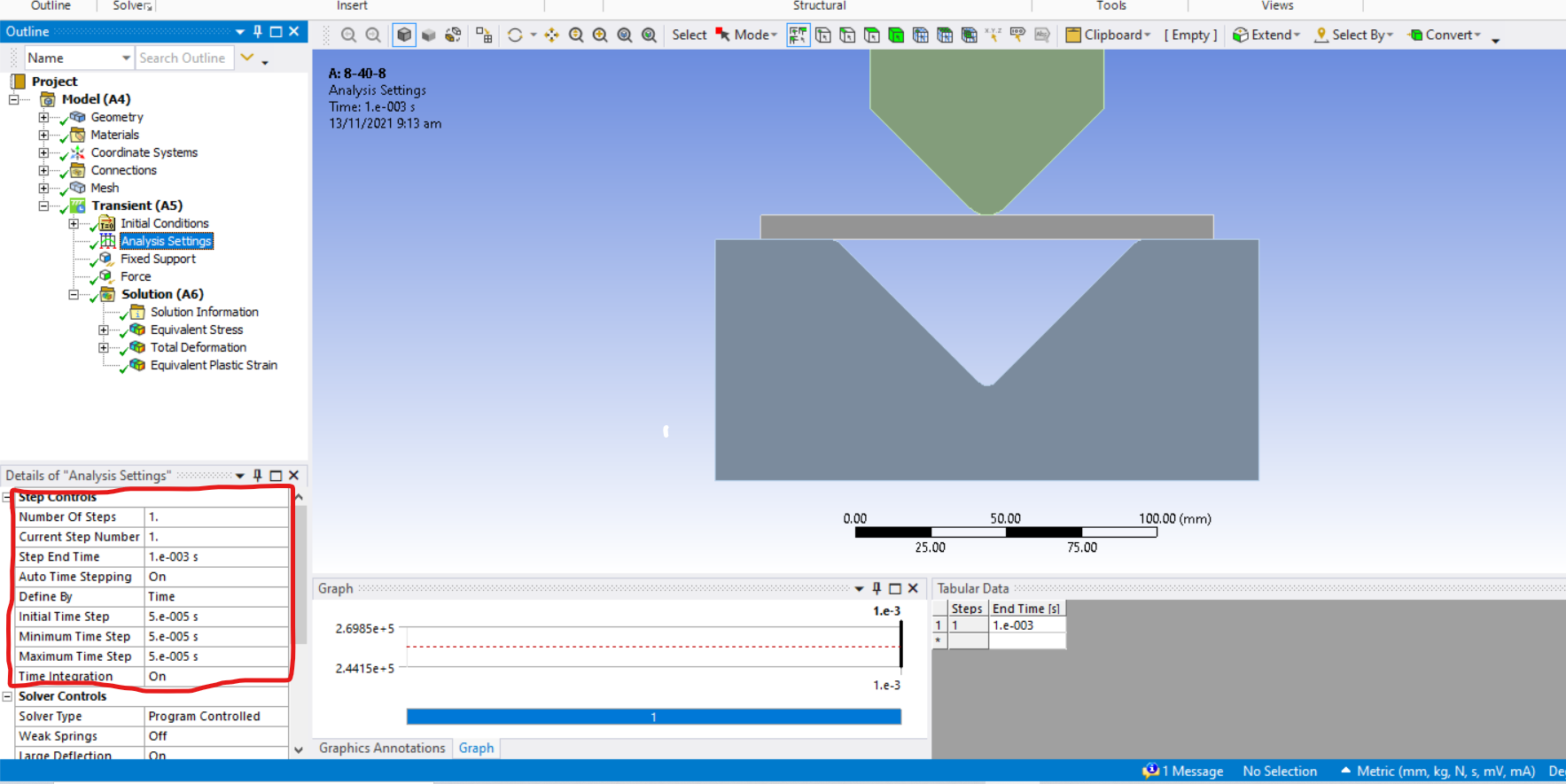 Sir i need to perform about 30 simulation on a plate bending but i really face a serious problem by assigning load force and Step End Time.I need to perform many simulations on a single plate just to know the convergence value of force and Step End Time for a particular plate.But when i perform simulation on a different dimension plate this load force and Step ENd Time does not work and does not converge.Then I need to perform many simulation on that plate.Which is very time consuming.Is there any way in Ansys that i could know i advance the value of appllied force and the Step End Time?
November 13, 2021 at 2:34 pmpeteroznewman
SubscriberDo not use a Force to bend the plate, use a Displacement to move the punch. Insert a Probe, Reaction Force into the Solution to plot the force used to bend the plate. This setup will be much easier for the solver to converge on and be robust to changes in plate dimensions.
December 12, 2021 at 5:39 amSubscriber I am not able to open the link,You have refered me.Needs such registration given in the above screenshot.
Could you please provide some guidence how to create different secton angles, such as at 0,10,20,90 degrees?
December 12, 2021 at 1:28 pmSubscriberDid you really want to share your phone number and email account with everyone on the internet? If not, you can request the image be removed in the Feedback part of the forum. /forum/categories/feedback
December 12, 2021 at 1:31 pmSubscriberoh gosh i did not notice that.I am sorry!
please guide me how to remove this picture?
December 12, 2021 at 2:01 pmSubscriberClick on the feedback link I provided, and create a New Question and request the image be removed. Insert a link to this discussion.
/forum/discussion/33301/measure-distance-between-two-ends-or-edges#latest
December 12, 2021 at 5:49 pmSubscriberI request please remove this photo,as it contains my personal contact information.
Thank you!
Viewing 17 reply threads- The topic ‘measure distance between two ends or edges’ is closed to new replies.
Innovation Space Trending discussions
 Top Contributors
-
peteroznewman
 4863
4863 -
scabo
 1587
1587 -
Dennis Chen
 1386
1386 -
javat33489
 1242
1242 -
Shyam Prasad V Atri
1021
Top Rated Tags
© 2026 Copyright ANSYS, Inc. All rights reserved.
Ansys does not support the usage of unauthorized Ansys software. Please visit www.ansys.com to obtain an official distribution.
-


The Ansys Learning Forum is a public forum. You are prohibited from providing (i) information that is confidential to You, your employer, or any third party, (ii) Personal Data or individually identifiable health information, (iii) any information that is U.S. Government Classified, Controlled Unclassified Information, International Traffic in Arms Regulators (ITAR) or Export Administration Regulators (EAR) controlled or otherwise have been determined by the United States Government or by a foreign government to require protection against unauthorized disclosure for reasons of national security, or (iv) topics or information restricted by the People's Republic of China data protection and privacy laws.


