-
-
March 13, 2024 at 8:40 am
Lee seyeon
SubscriberÂ
Hi, I simulate coils to study, but it has errors
Â
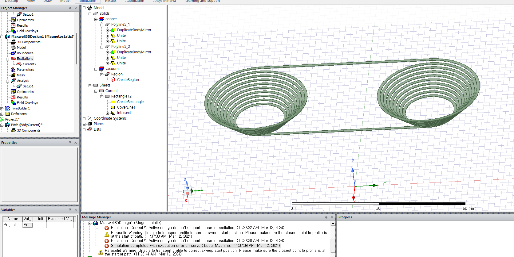
Excitation 'Current7' : Active design doesn't support phase in excitation.
Then when I add another coil, another error occur
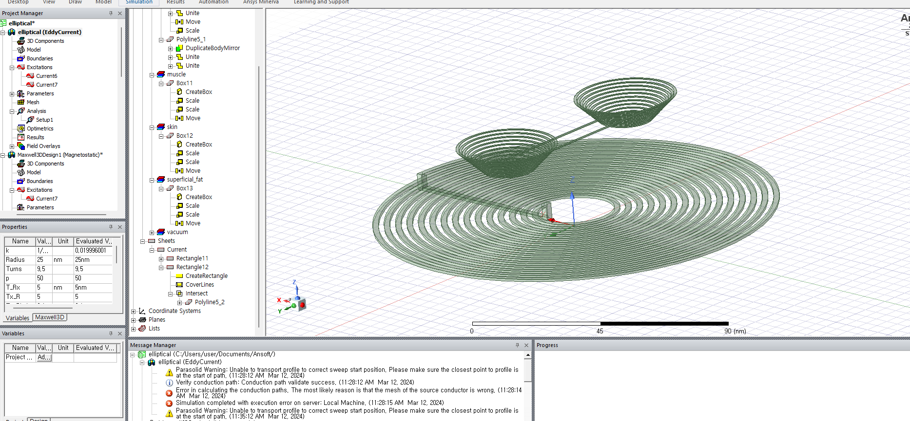
error in calculating the conduction paths. The most likely reason is that the mesh of the source conductor is wrong.
why these errors occur? and how can I solve it?
-
March 16, 2024 at 2:37 am
GLUO
Ansys EmployeeHi,
Are you using 2023R1 version? It seems the solver is not happy with the geomtry/mesh. Please try in 2024R1, the newest version of Maxwell, has some improvement on mesh method for Parasolid kernel geometries introduced in 2023R1 version.
GL
-
March 21, 2024 at 1:43 am
Lee seyeon
SubscriberThank you for your response.
I use student electronic free software, so I can't use 2024R1. Can I solve it in 2023R2?
Â
thank you.
-
March 21, 2024 at 3:58 pm
GLUO
Ansys EmployeeI would recommend go to model to purge the history for all objects, then export them as STEP file, and re-import them to reformat the geometry. But before doing this, please double check if the issure is from other aspect, you can follow these steps:
1. Verify the conduction path and ensure that the excitation terminal perfectly covers the conductor cross-section. This is especially important if the conductor has a complex geometry that is challenging to mesh [1]. URL: [1] /forum/forums/topic/maxwell-eddy-current-solver-simulations-execution-error-current-leaks-in-air/
2. If the issue persists, you can force a recalculation of the conduction paths. This can be done by using the Maxwell>Excitations>Conduction Paths>Recalculate Conduction Paths command. This command recalculates every time, even if there are no changes that influence the conduction paths [2]. URL: [2] https://ansyshelp.ansys.com/account/secured?returnurl=/Views/Secured/Electronics/v232/en/home.htm%23../Subsystems/Maxwell/Content/RecalculatingConductionPaths.htm?TocPath=Maxwell%257CMaxwell%2520Help%257CAssigning%2520Boundaries%2520and%2520Excitations%2520for%25203D%2520Designs%257CShowing%2520and%2520Verifying%2520Conduction%2520Paths%257C_____1
3. If the error is due to a low material conduction, you can manually adjust the material threshold to a suitable value that considers the conductivity of the material [3]. URL: [3] /forum/forums/topic/fatal-error-in-a-dc-conduction-model-when-material-conduction-is-too-low/
4. In some cases, configuring the winding type as stranded can resolve the issue [4]. URL: [4] /forum/forums/topic/how-to-do-the-winding-excitation-for-maxwell3d-transient-design/
-
- The topic ‘maxwell : why this error occurs?’ is closed to new replies.
- Y wiring method and the start and end points of winding.
- Lumped Port Deembed
- Optimizing Via Impedance in Ansys HFSS 3D Layout Using Geometric Parameter Sweep
- Hfss 3D pcb via capped and filled with epoxy
- AEDT Natural Convection with default correlation is failing solver initializatio
- HFSS libnvidia-ml.so too old or could not be found – Warning in slurm job output
- Three-Phase Voltage Imbalances in dual stator electric generator
- STL Import Errors in HFSS After Cleaning in SpaceClaim
- Calc Error in Field Calculator after PyAEDT Analyze
- import file autocad 3d
-
3887
-
1414
-
1241
-
1118
-
1015
© 2025 Copyright ANSYS, Inc. All rights reserved.