Hi, I setup the simulation for transient. I have a few basic questions.
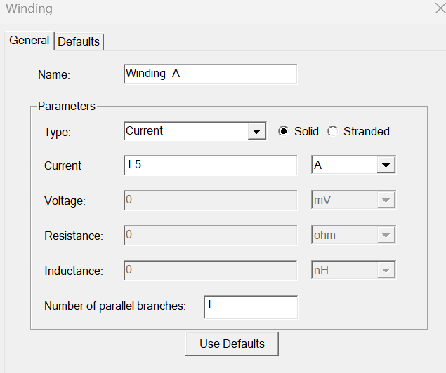
1. If I want the coil to be excited by DC current of 1.5 Amps, would the settings below be correct? I chose solid since the copper wire used in the winding is of type solid.
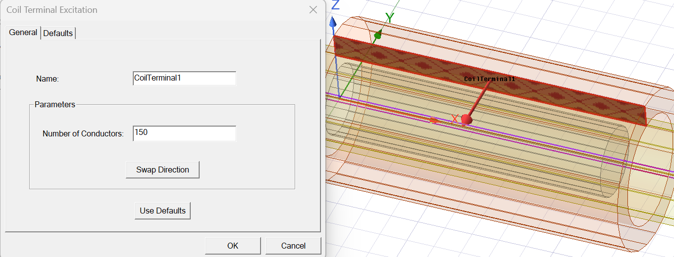
2. For the “Coil Terminal Excitation” should the number of conductors be set to 1 if we chose solid type for the winding?
3. I have noticed that in most Maxwell transient simulation tutorials and workshops on the Learning Hub, the parameter "number of turns" for the coil winding is not defined or mentioned. This was not the case for Magnetostatic workshops. Why is this?
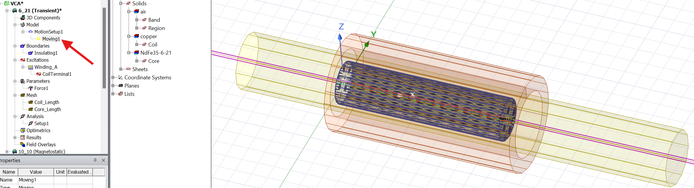
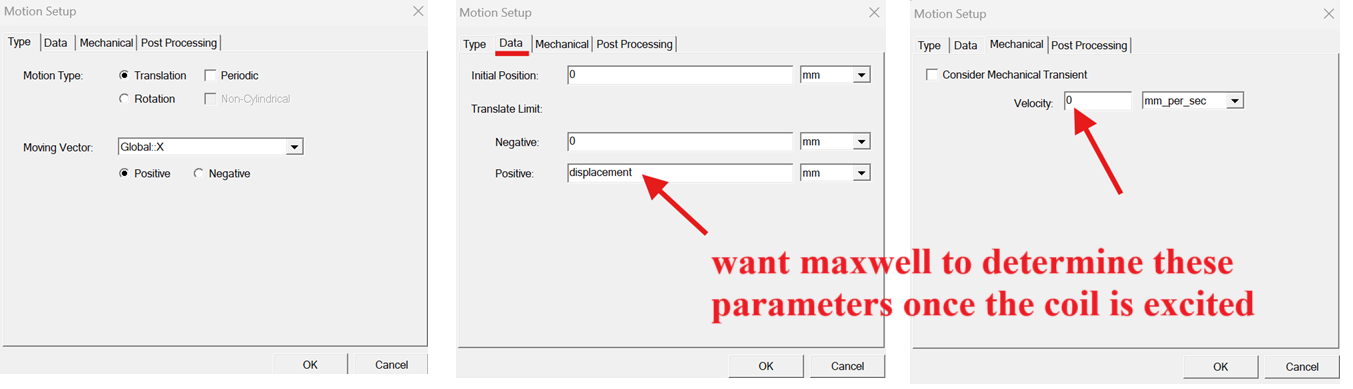
4. Continuing with the transient simulation, I assigned motion setup to a cylindrical Band. The moving component will be a cylindrical PM (as seen below). However, what if I wish Maxwell to determine the velocity and displacement (translation in either positive or negative direction) of the PM instead of me entering these values? The reason I’m asking this is because I performed an experimental setup, and as soon as the coil winding is excited the PM shoots into the coil winding at some speed which I don’t know. Furthermore, the amount by which the PM is displaced varies as the input current changes. Entering an arbitrary value for "velocity" and "translation limit" during the motion setup defeats the purpose of running the simulation because I wish Maxwell to populate Velcocity and/or Displacement vs Time plots.