-
-
February 15, 2024 at 4:58 pm
Nick Husic
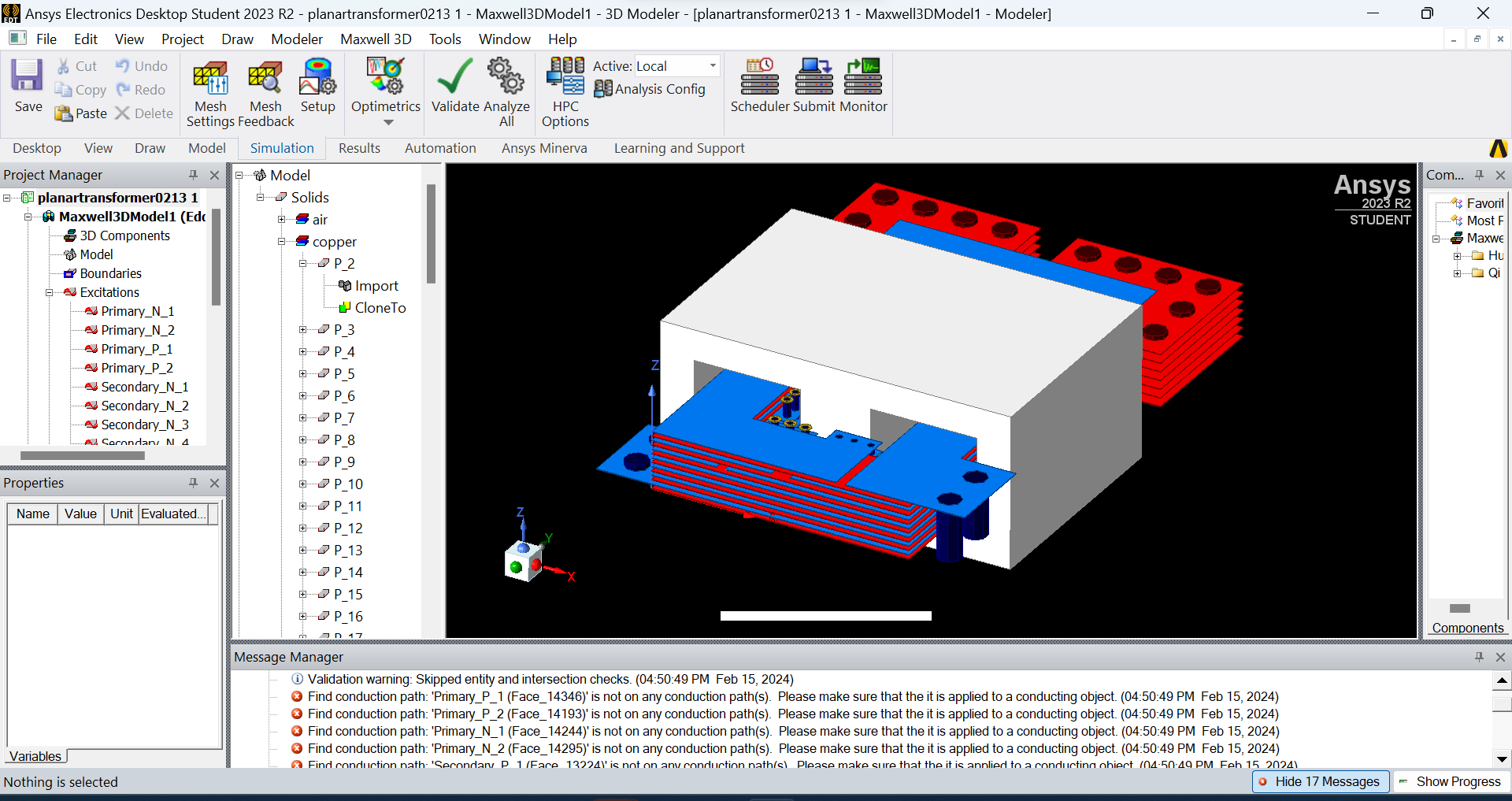
SubscriberI am new to Maxwell, simulating a planar transformer. I imported the PCB from Altium and am doing eddy current analysis. The primary (blue) and secondary (red) are excited through the large vias in dark blue and red. I have created an air box which is trimmed such that the faces of the vias to be excited are touching the edge. There should be two conduction paths going through primary and secondary coils, with both paths being driven by multiple parallel current excitations on all the large vias. When I validate, I get the error shown at the bottom of the screenshot saying that the conduction paths cannot be found. I have never done this before and want to know if I can manually define the conduction paths, or if importing from Altium is causing a problem. Thanks
-
February 22, 2024 at 11:55 am
Reshmi Raghavan
Ansys EmployeeHello Nick,
As per the shared figure I can find two winding in primary (P_1 N_1,P_2N_2) and secondary. Please check if the copper parts part of the connection from P_1 to N_1 are all connected through magentic parts and forming a conduction path, similarly for other windings too.
As per the error message the face on which the terminals are defined is not on the conduction path. The face selected to specify the in and out terminal should be lieing on the face of the Region.
-
March 20, 2024 at 4:58 pm
Andres Nader
SubscriberHi, Im having the same problem with a 3D simulation. How can I quick check the conduction paths?
-
March 20, 2024 at 5:04 pm
Nick Husic
SubscriberYou can check the paths by right clicking excitations and going on conduction paths. I solved it by selecting all the conducting objects and changing the material to something else like diamond. I then changed it back to copper and it worked. This issue is likely due to importing the model from Altium, so if you didn't do that I'm not sure this will help.
-
-
- The topic ‘Maxwell 3D ‘Find Conduction Path’ Error’ is closed to new replies.


-
4683
-
1565
-
1386
-
1242
-
1021

© 2025 Copyright ANSYS, Inc. All rights reserved.


