TAGGED: workbench
-
-
October 20, 2025 at 8:23 am
Marharyta.Miednikova
SubscriberHello everyone.
I am working in Explicit Dynamic in Workbench.
Does anyone knows what does mean the maximum and the minimum velocyties of the node (or a body) in every time step? why there are no just maximum? what should be analysed: maximum velocity or average?I will apriciate your help to understand
Thank you -
October 20, 2025 at 1:30 pm
Armin
Ansys EmployeeHi Marharyta,
In Ansys Workbench, the maximum, minimum, and average results (such as velocity and stress) are displayed for every time step. These are referred to as the maximum, minimum, or average results for the entire scoped body for the specific time. When analyzing these results, it is important to consider the context and purpose of the analysis. For example, the maximum stress might be more relevant for understanding areas with the highest risk of failure, while the average values provide a better understanding of overall system behavior. -
October 21, 2025 at 4:55 am
Marharyta.Miednikova
SubscriberHello.
Thank you for reply.
I am afraid im still not clear about it.
Stresses are caluclated in the integrational points of the element. So, when we display maximum stress it means maximum among integrational points, average stress - ansys takes into accounts strsses of the elements next to considered element and display average result. Then, if to display element results without average, it will show stress in the integrational points.
But it is not clear how does it link ith velocity results.
In explicit dynamic, my body is rigid, so element have only one integrational point. So, what does mean rage of velocity in the node or in the body (range i mean from minimum to maximum)?
In my results,maximum velocity looks correct, but if to consider average result it is lower by 30% then supposed to be. It confuses.
Thank yuou -
October 21, 2025 at 1:43 pm
Armin
Ansys EmployeeThank you for providing more information.
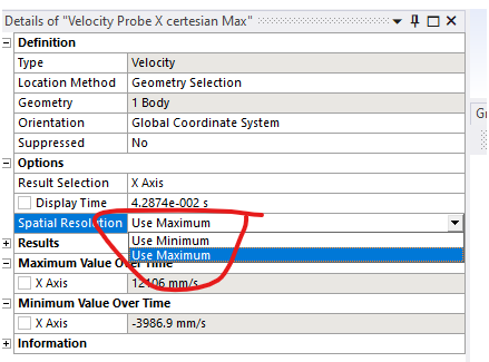
The maximum/minimum results discussed in my previous message are related to nodal results, which indicate the maximum/minimum/average values "over an entire body". This is different from the averaging scheme used to display the results. For your reference, this option is also accessible under the details window as "Display Option" for flexible bodies.
However, since you indicated that your body is rigid, there should be no relative movement between nodes within the body, since by definition all points in a rigid body move together as a single unit without deforming (i.e., there should be no difference between minimum, maximum, and average values). Could you check if the body is properly set to have rigid behavior? Also, if you have any screenshots of the model or results, they would be helpful.
-
October 22, 2025 at 5:30 am
Marharyta.Miednikova
SubscriberDear Armin,
Thank you for your reply.
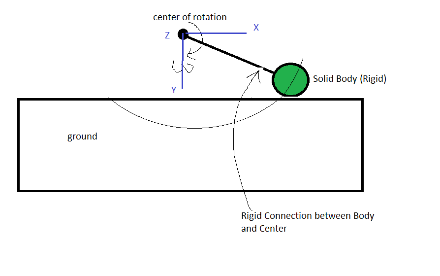
Model in brief:Rigid body rotates around the center of rotation with controled velocity (by motor).
Body cuts ground.
Center of rotation is remote point.
Global coordinate system is located in center of rotation. Body rotates around Z axis.
Since, explicit dynamic in WB does not have option to apply contsant angular velocilty to body, so I have applied “rotation (deg) vs time” as “remote displacement” boundary condition.
Body rotates by 180 deg.
Movement of body starts from the position of touching the ground.
So, Time “0” – body strats penetrate into ground,
Time “8.5724e-2″ – body have rotated by 180 deg.
Also, ansys does not transfer velocity results in cylindrical CS. So, I linear velocity along X and Y axes extruded, then I convert it into angular velocity.
If to consider Total Maximum Velocity, it matches with value of “A = angular velocity multiply by radius of rotation”.
But, if to consider Total Average Velocity, it much less then A.
This is confused…
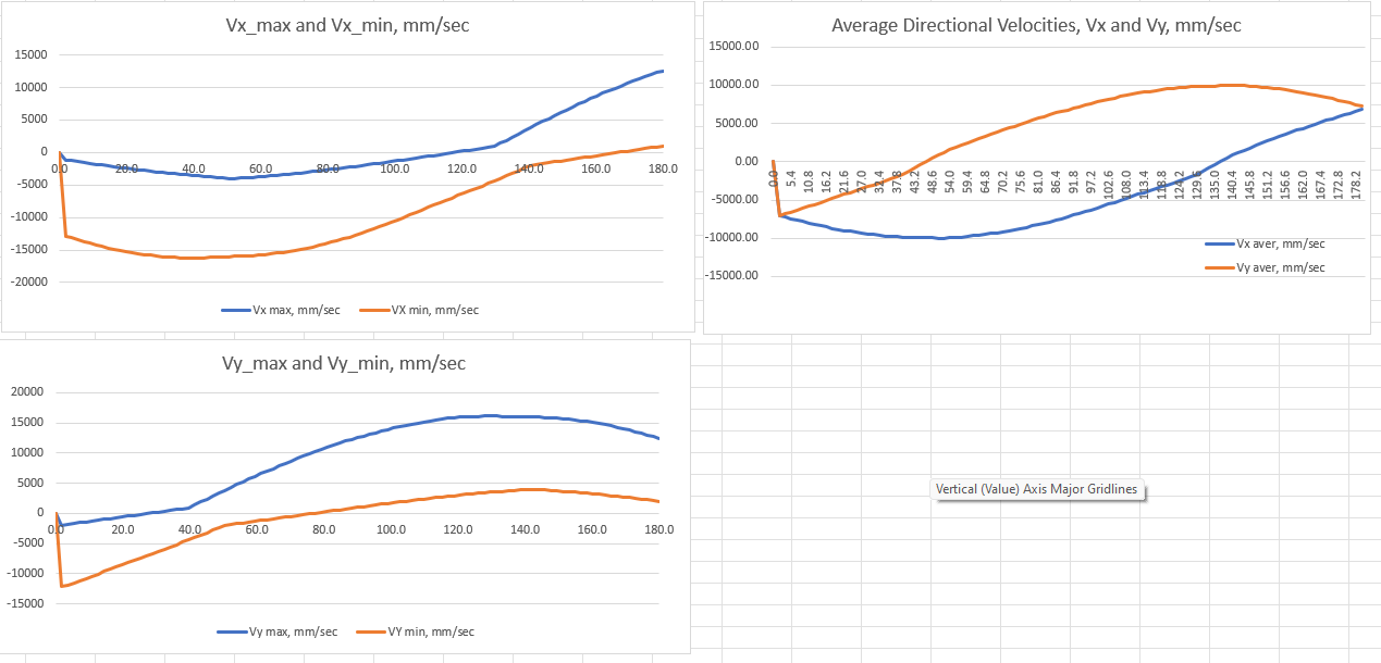
Graphs of Total and Maximum/Minimum/Average Velocity for the body are attached.
Maximum and Minimum velocities are built in excel just for better visualization.Where X axis is degrees of rotation instead of time. So, zero degree means body touching the the ground, 90 deg – body left ground, and from 90 to 180 deg – body rotates in the air
Thank you in advanced
I apprecite your time to consider it -
October 22, 2025 at 3:18 pm
Armin
Ansys EmployeeThanks Marharyta.
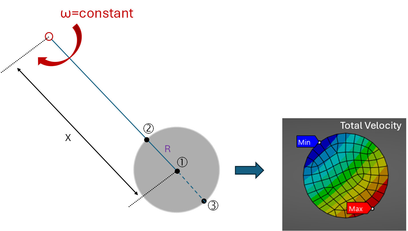
Note that the radius of rotation in the formula (angular velocity multiplied by the radius of rotation) depends on the location of the node. I believe this is the reason you observe different magnitudes for the minimum, maximum, and average values of total velocity. For example, if the distance from the center of rotation to a circle with a radius of R is X, the maximum and minimum velocities will occur at (X + R) and (X - R), respectively.
You didn't mention about the interaction of the rigid part with the ground. If the ground and its interaction with the rigid body are not modeled, you might consider applying "angular velocity" as an Initial Condition (refer to the screenshot below). I believe this approach will simplify the calculations.
-
October 23, 2025 at 5:01 am
Marharyta.Miednikova
SubscriberHello Armin.
Reqarding Angular veloctyas Initial Condition. This option is not the same. This option is is for velocity at the first point, then body has free movement. However, my body is rotated by motor with constant angular velocty.
Reqarding interaction of the body. Yes, it is modeled.
Sorry, I could not understand idea about minimum and maximum... Could you please explain more? I am confused a bit. Ansys calculate position of node in rectangular coordinate system (x, Y), but radius is fixed during movement...what did you mean by X+R and X-R?
Thank you -
October 23, 2025 at 2:37 pm
Armin
Ansys EmployeeHi Marharyta,
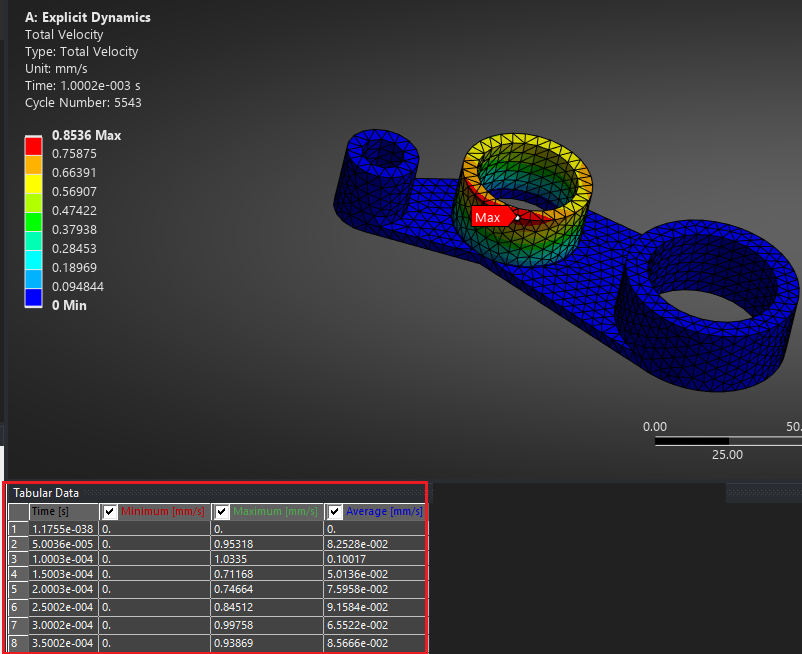
Regarding your question, the angular velocity is constant, but the distance to the center of rotation is not. Please refer to the schematic below: at point 1, the velocity is RW, but it should be (X-R)W at point 2. Similarly, the velocity will be (X+R)W at point 3. This leads to variations in the total velocity contour (despite the constant angular velocity), as shown in the image below.
-
- You must be logged in to reply to this topic.


-
4152
-
1487
-
1318
-
1170
-
1021

© 2025 Copyright ANSYS, Inc. All rights reserved.

