

TAGGED: peteroznewman
-
-
July 9, 2021 at 7:43 pm
fea11
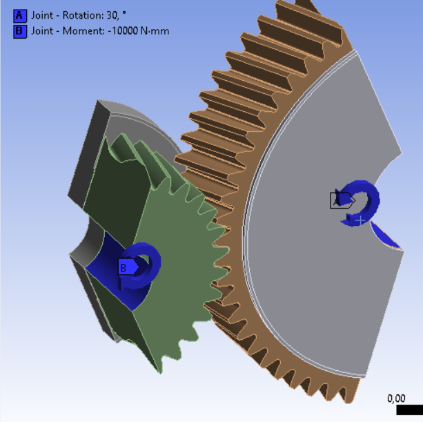
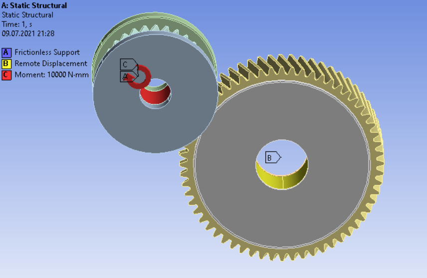
SubscriberI am simulating a thrust cone bearing with boundary conditions as in the picture and wanted to check if my physics is correct, so I used the default mesh. The problem is that my solver is stuck at 1% for 2 hours even after unchecking the distributed it didn't help. I have also this warning message "One or more remote boundary conditions is scoped to a large number of elements which can adversely affect solver performance. Consider using the pinball setting to reduce the number of elements included in the solver."
Can anyone suggest some solution? Or maybe better boundary conditions?
I tried uploading zip file after clearing all data but I couldn't do it.
July 11, 2021 at 11:42 amSubscriberHello I tried to simulate using revolute at both gears and then using joint load. But now I have a problem with insufficient RAM (that must not be the case as I am using a PC from my university which is faster and has sufficient RAM). I got 2 Warnings and 1 error. I tried to solve with fixed boundary condition to recheck on warnings
and errors and then there wasn't such a problem.
Can anyone help me out, with what am I doing wrong with boundary conditions?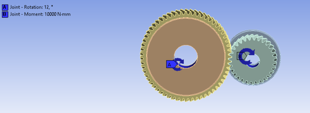
July 12, 2021 at 12:40 ampeteroznewman
SubscriberIn these images of spur gears, you can see that only a portion of the gear has been modeled. This is a good way to greatly reduce the number of elements in your model. I suggest you do the same for your helical gears.

 July 12, 2021 at 7:17 amSubscriberdid you use cyclic symmetry here? If yes, then I don't think that should not be the case for helical gear. And Is there any way to cut my model like this in design modeler or SpaceClaim?
July 12, 2021 at 12:53 pmSubscriberNo cyclic symmetry was used. All the interesting stress is at the few teeth in contact. A few teeth away from that there is nothing much to see.
In SpaceClaim, create a plane through the center and rotate it to the angle you want using the Move Tool, then use Split Body.
July 12, 2021 at 2:01 pmSubscriberThanks for the suggestion. I did as you suggested. Moreover, I have also rechecked the contact gaps, but i am still facing the problem. I have uploaded the .wbpz file and if possible could you please have a look at it.

July 12, 2021 at 11:12 pmSubscriberWhat version of ANSYS are you using?
July 13, 2021 at 8:30 amSubscriberI am using Ansys2020 R1 academic/commercial version. Is there any problem?
July 13, 2021 at 4:50 pmSubscriberSorry, it's Ansys2020 R2.
July 14, 2021 at 8:11 pmSubscriberIt is a good idea to put the version you are using anytime you attach a file because I can't easily tell when I download which version it came from. In your other discussion, I showed a mesh that was done in ANSYS 2021 R1 which you can't open.
Also, since you have two discussions going and you didn't use in this post, I was not notified when you replied with the version in this thread when I was answering in the other thread.
July 15, 2021 at 7:20 amSubscribersorry I didn't know about it. Did you check what's wrong with the boundary conditions in the model, any suggestion would be helpful?
July 15, 2021 at 1:41 pmSubscriberHello Peter, I have opened your file in the 2021 version and thanks for your very detailed geometry, but there is a problem that thrust cones aren't flat rather they must touch at some angle and have very small maybe 0.05mm and what you see in the picture are exaggerated.
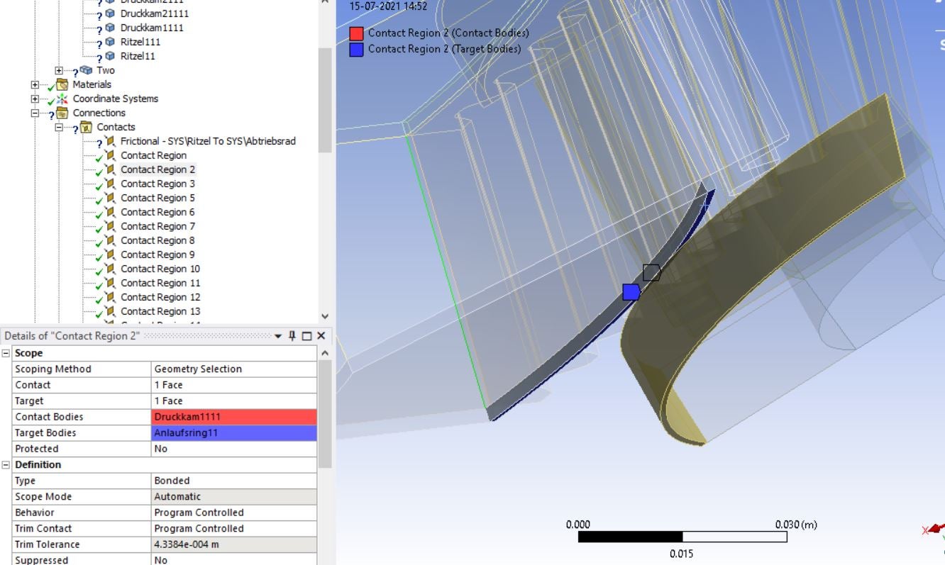
Could you tell why have you used bonded connection instead of frictionless, as the two thrust cones must slide over each other?
July 15, 2021 at 8:45 pmSubscriberI didn't know about the small conical angle on that face, but you can put that in.
I understand those surfaces slide on each other. When I made the geometry changes, I only paid attention to the mesh, I didn't pay attention to the contacts. ANSYS automatically makes all those contacts, those are not coming from me. Most of those can be deleted and what you want carefully created. There is an option in Workbench to turn off the automatic creation of contacts. That is my preferred setting, but I haven't configured this version with that setting yet.
July 16, 2021 at 7:06 amSubscriber% since I really want to know about the boundary conditions, if they are correct. When I am solving, the mathematical model is still stuck at 8% for 10 hours. I am using joint loads instead of remote displacement. Do you have any suggestions why its happening?
July 16, 2021 at 10:51 amSubscriberI suggest you break the problem down into component pieces. First have a model with no thrust cone bearing that just has the helical teeth. The joints connected to the hole in the center of the gear will support and measure the axial force the helix generates. Or maybe you calculate that thrust force from equations. Second, have a model where the axial force is applied to the contact area of the thrust cones, and a tangential force to represent the friction. There is no contact in the model for the thrust cone. Each joint only holds a small cylindrical face at the center of each gear.
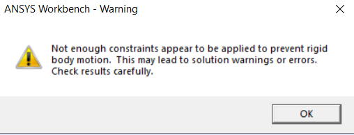
July 18, 2021 at 9:24 amSubscriberI suppressed the thrust cones and solved just for helical gears using the body to ground revolute joints and again I am getting constraint warning "Not enough constraints appear to be applied to prevent rigid body motion.This may lead to solution warnings or errors.Check results carefully." I am clueless why it's happening, as a revolute joint only allows rotation of the body about Z-axis (I've chosen).
Using Ansys 2020 R2 version.

July 18, 2021 at 1:34 pmSubscriberThe solver often issues this warning. I see it when the structure has exactly the correct connection to ground to prevent rigid body motion so it should not issue that warning, but since I know the constraints are correct, I can ignore the warning. In your case, rotation about the revolute axis is free so the warning is issued. But you know that the contact at the teeth are going to support that rotation so you can ignore the warning.
Thank you for labeling the ANSYS version with the release number for the attached archive. That lets me know to start that version to open the archive and send it back to you in the same version! Since I only have the Academic license for 2020 R2, I can't solve your model.
 I don't know if the model converges and you are just asking about the warning, or there is still an issue.
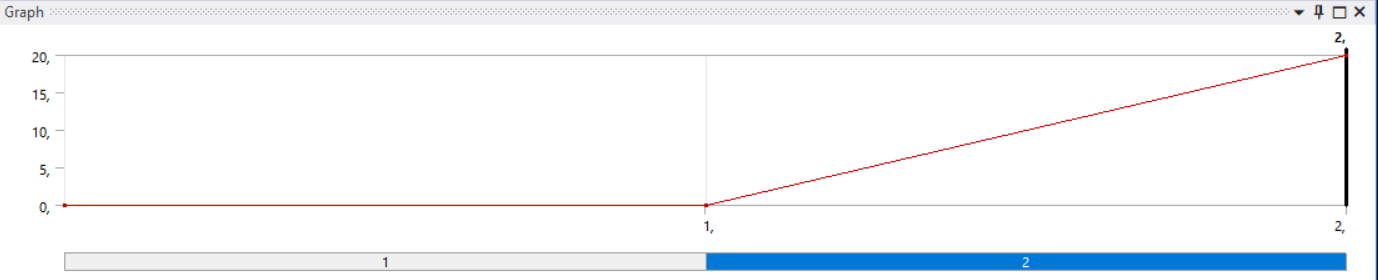
I did notice two things that you may want to change. I see you have a 20 degree rotation that ramps from 0 to 20 over Step 1, which is fine, but you also have a Moment that ramps from 0 to 1 N-m over the time step. I suggest that what you may prefer is to change this to a 2-step simulation. In Step 1, hold the rotation at 0 degrees while the Moment ramps up to 1 N-m, then in Step 2, rotate the other joint while holding the Moment constant at 1 N-m. The other change is to use the Direct solver instead of the Iterative solver.
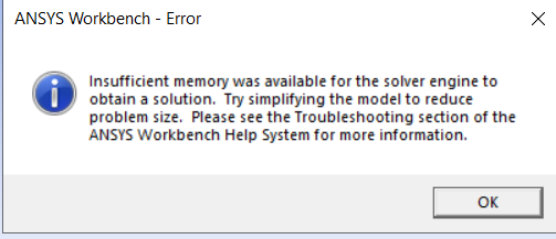
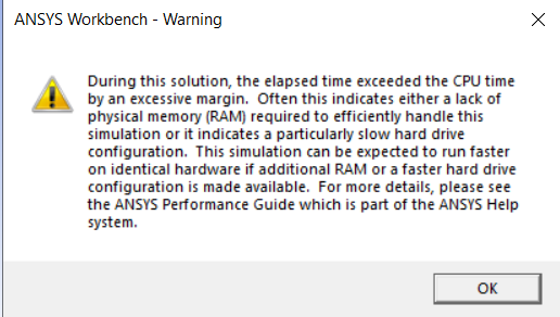
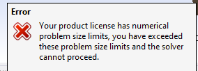
July 19, 2021 at 8:42 amSubscriberI did the step loading but the model fails to converge with error "insufficient memory was available for the solver engine to obtain a solution.Try simplifying the model to reduce problem size.Please see the Troubleshooting section of the ANSYS Workbench Help System for more information." and with a warning "During this solution, the elapsed time exceeded the CPU time by an excessive margin.Often this indicates either a lack of physical memory (RAM) required to efficiently handle this simulation or it indicates a particularly slow hard drive configuration.This simulation can be expected to run faster on identical hardware if additional RAM or a faster hard drive configuration is made available.For more details, please see the ANSYS Performance Guide which is part of the ANSYS Help system."
I am using the university's PC with 16 GB RAM and SSD.

July 20, 2021 at 9:49 amSubscriberare these boundary conditions good for a static torque test? Or I must try using fixed boundary on driven gear?
July 20, 2021 at 11:48 amSubscriberThose are good boundary conditions.
The solver did not fail to converge, it could not start solving at all because there was insufficient RAM.
The university should install more RAM in the PC that runs ANSYS. 16 GB is inadequate. 64 GB would be better.
How many nodes are in your mesh? You can try reducing the number of nodes in the mesh.
You can try switching the Solver from Direct to Iterative.
July 21, 2021 at 4:56 pmSubscriberMany thanks for your help as reducing the nodes solved the problem. But I have one question, when I used 100 substeps it leads to convergence failure as according to the solver there was too much penetration at contact points Ansys. But reducing the no. of substeps to 10 converged it. So, will using less no. of substeps give accurate Stresses and deformation in the model?
July 21, 2021 at 10:17 pmSubscriberNo, every converged substep has the same accuracy criteria. It doesn't matter if the number of substeps was 10 or 100.
July 26, 2021 at 7:00 amSubscriberI tried with different rotations like from 20┬░ to 5┬░. There is a big difference in stresses obtained from different rotations. I read your discussion /forum/discussion/1381/spur-gear-analysis but the bending equation or Hertzian pressure shouldn't depend on the rotation of one gear. How one can determine analytically whether the Ansys results are correct as the stresses keep changing with degree of rotation?
July 26, 2021 at 1:01 pmSubscriberDid you read the part where I said, "Thiswebpagehas an excellent animation that you must watch. The worst case for stress may not be when the contact is at the pitch circle."?
A big difference in stress is expected when the rotation angle changes because the contact point moves in and out from the pitch circle. The bending equation depends on the actual location of the contact point which is moving with rotation angle.
There are no analytical equations for the stress in a helical gear, you have to rely on numerical simulations.
There are analytical equations for simpler geometry like a four point beam bending geometry. Ansys simulations have very close agreement with those equations.
Viewing 23 reply threads- The topic ‘Mathematical model stuck at 1% with a warning of remote displacement’ is closed to new replies.
Innovation Space Trending discussions
 Top Contributors
-
peteroznewman
 5734
5734 -
scabo
 1906
1906 -
Dennis Chen
 1419
1419 -
javat33489
 1305
1305 -
Shyam Prasad V Atri
1021
Top Rated Tags
© 2026 Copyright ANSYS, Inc. All rights reserved.
Ansys does not support the usage of unauthorized Ansys software. Please visit www.ansys.com to obtain an official distribution.
-


The Ansys Learning Forum is a public forum. You are prohibited from providing (i) information that is confidential to You, your employer, or any third party, (ii) Personal Data or individually identifiable health information, (iii) any information that is U.S. Government Classified, Controlled Unclassified Information, International Traffic in Arms Regulators (ITAR) or Export Administration Regulators (EAR) controlled or otherwise have been determined by the United States Government or by a foreign government to require protection against unauthorized disclosure for reasons of national security, or (iv) topics or information restricted by the People's Republic of China data protection and privacy laws.
