-
-
February 17, 2023 at 7:13 am
Krishan Kant
SubscriberIs there a way to utilize the periodicity of a linear motor by master/slave boundary condition?
I am using magnetostatic simulation and I want to move the mover to obtain force.
I assigned the BC to a bounding box for the motor, but it doesn't work when the mover moves.
I tried various M/S conditions for each component, winding, yoke, magnet; but when mover moves, I dont see a symmetric field pattern.
How to do that?
Thanks
-
February 21, 2023 at 3:31 pm
HDLI
Ansys EmployeeHello Krishan,
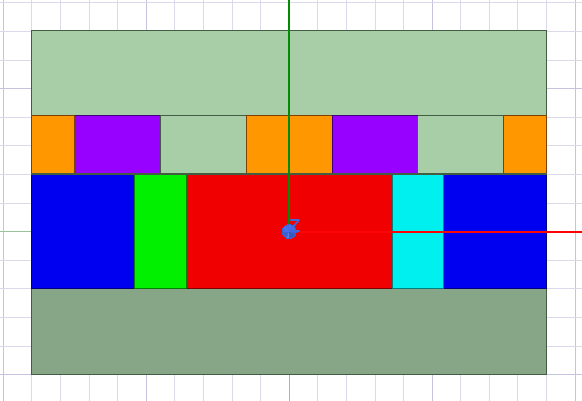
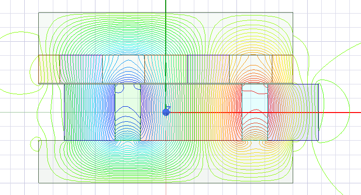
We could use masking geometry to complete the movement in magnetostatic solver, that do not support motion.
1). Build a long rotor with material assingment, and magnet direction should be moving CS of ticking on "Move CS to end" in CS properties.
2). Add moving parameter on the whole rotor (moving parts), "Move" whole rotor and enter the parameter as moving value.
3). Build two regions (masking geometry) to cover outside of two ends of linear motor.
4). Subtract masking geometry from the whole rotor.
5). Set matching boundary with same vector
6). select "igonre Unclassified objects" in Maxwell 2D -> Design settings -> Validations.
After that, modify the miving parameter to check if model is correct.
There is in Ansys customer portal, https://support.ansys.com/KnowledgeResources/Solutions?solutionIdentifier=sol2043350&productName=ANSYS+Maxwell&productFamily=Electronics
Howard
-
March 20, 2023 at 12:01 pm
Krishan Kant
SubscriberThank you Howard,
I ran into another issue with these simulations.
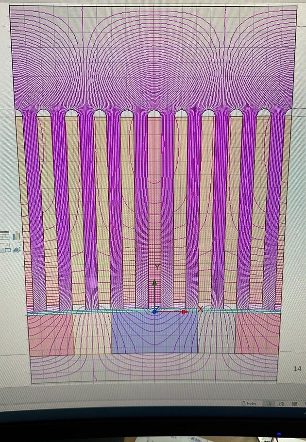
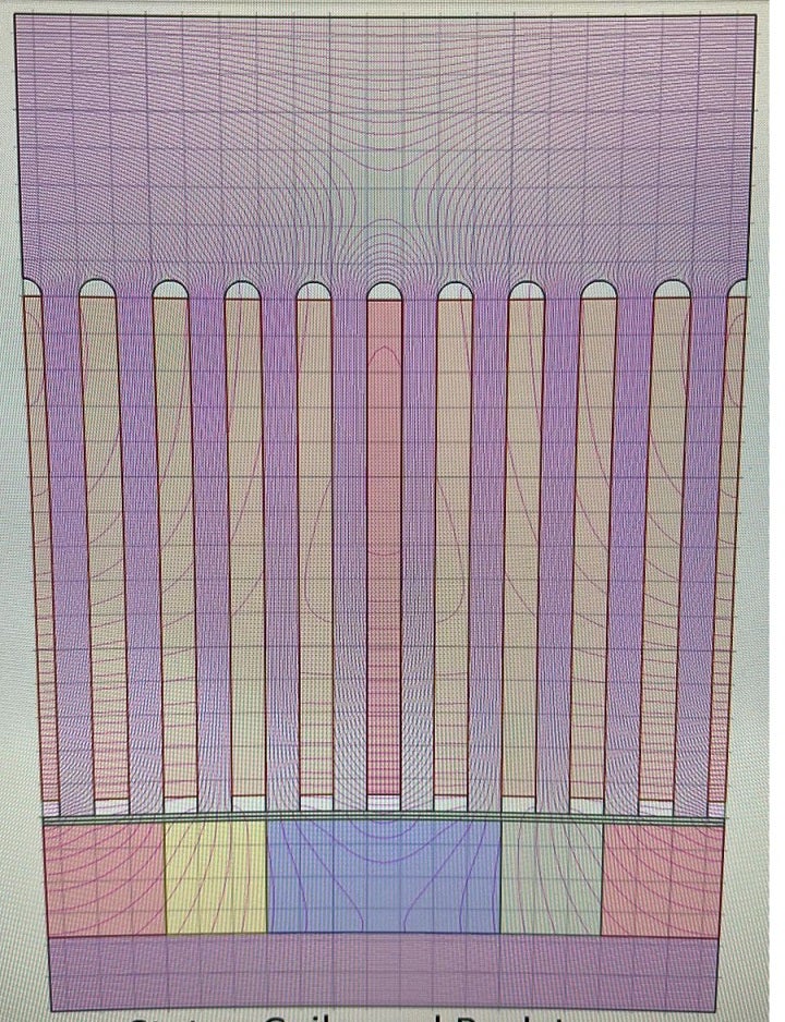
The BC behaves differently if I create a small model (1 period) vs if I create a full model and subtract the extra parts of the model to obtain 1 period of the motor. The flux distribution is wrong for the case where I am subtracting the masking rectangles from the full model. This is the only difference in the models. Everything else is same. Here are the pictures. Top picture has a smaller model. Bottom one is subtracted full model.
Thank you
-
- The topic ‘Master Slave Boundary condition for linear motors’ is closed to new replies.


-
4728
-
1565
-
1386
-
1242
-
1021

© 2026 Copyright ANSYS, Inc. All rights reserved.


