TAGGED: massconservationcheck
-
-
October 3, 2024 at 2:03 pm
ghislain_madiot
SubscriberDear ANSYS Support Team,
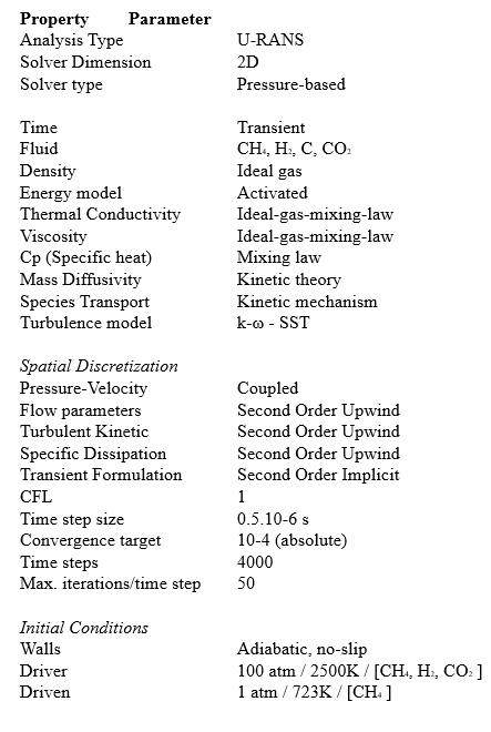
I am working on replicating a shock tube experiment for methane pyrolysis in ANSYS Fluent. To simplify the process, I initially set up a basic simulation before incorporating a complex kinetic model. The reaction I'm modeling is methane pyrolysis using a one-step kinetic reaction with the following parameters:
- Reaction: CH₄ → 2H₂ + C
- Pre-exponential factor: 606800
- Activation Energy (J/kmol): 1.852e+8
- Temperature exponent: 0.1
Problem Overview:
For the initial conditions, I set the driver gas at 100 bar and 2500K and the driven gas at 1 bar and 723K. My domain is defined as a simple shock tube with driver and driven sections, surrounded by walls. I utilized mesh adaptation to track the shock, based on a curvature of pressure.
My first run was done without including the kinetic reaction to ensure the basics—such as mesh, mass conservation, and shock behavior—were functioning correctly. All basic checks appeared successful.
However, upon testing different driver gases [CH₄,CO₂ or H₂] and applying the following conditions:
- Driver: gas at 2500K and 100 bar
- Driven: CH₄ at 723K and 1 bar
I encountered an issue with mass conservation in the closed system.
Issue:
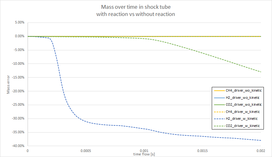
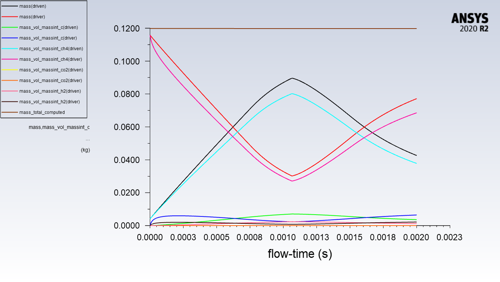
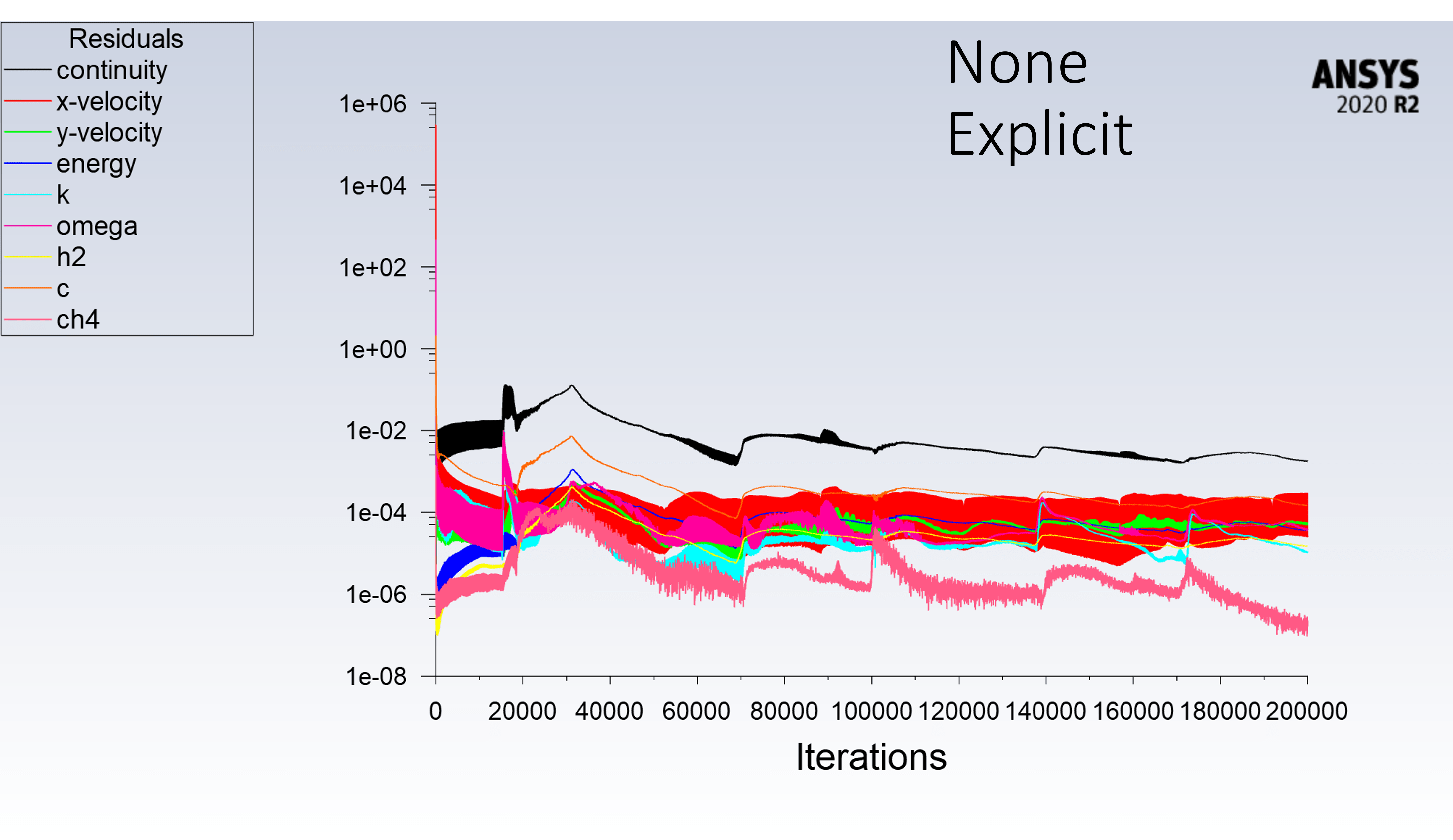
Despite trying various numerical parameters, I continue to experience mass conservation errors over time, as shown in the attached figure. I'm surprised by this result, particularly since the residuals for continuity seem to converge (with values below 0.001 absolute). Note that the simulation with CH₄ as driver has no mass issue.
Question:
Could you please provide guidance on the appropriate numerical parameters or settings I should use to resolve this mass conservation issue? Any insights into why the continuity residual converges but mass conservation errors persist would be greatly appreciated.
Thank you for your assistance!
Best regards,
Ghislain -
October 10, 2024 at 11:43 pm
vinaraya
Ansys EmployeeHi Ghislian,
I would like to know a few more details:
a) are the walls adiabatic ? and how is the energy conservation for all the 3 cases.
b) Could you share a snippet of the density contour for the 3 reacting cases before and after the point the mass imbalance increases.
c) Will the CH4 case also show mass imbalance if run further because i could see for H2 imbalance started at ~0.25ms and for CO2 case at 1ms
d) what are the mach numbers expected in the simulation and could you also share the residual plots for either of the H2 and CO2 case.
e) Could we try with Segregated solver and FO schemes and see if the results improve ?
-
October 10, 2024 at 11:46 pm
vinaraya
Ansys EmployeeI just noticed that you had already mentioned that the walls are adibatic. Is this choice accurate or should it have a non adiabatic BC ?
What is the change in pressure and temperature within the domain once the reaction starts. Could you share snippets of temp and pressure contours for CH4, H2 and CO2 driver cases (at points before and after the mass imbalance appears).
-
October 25, 2024 at 12:36 pm
ghislain_madiot
SubscriberHi Vijay
a) Are the walls adiabatic? Additionally, could you explain how energy conservation is managed across all three cases?
Wall are adiabatic for all cases
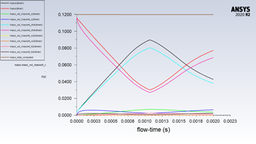
b) Could you provide a snapshot of the density contour for each of the three reacting cases, both before and after the point where the mass imbalance begins to rise?
Attached is the relevant snapshot.
c) If the CH₄ case were to run longer, would it also show signs of mass imbalance?
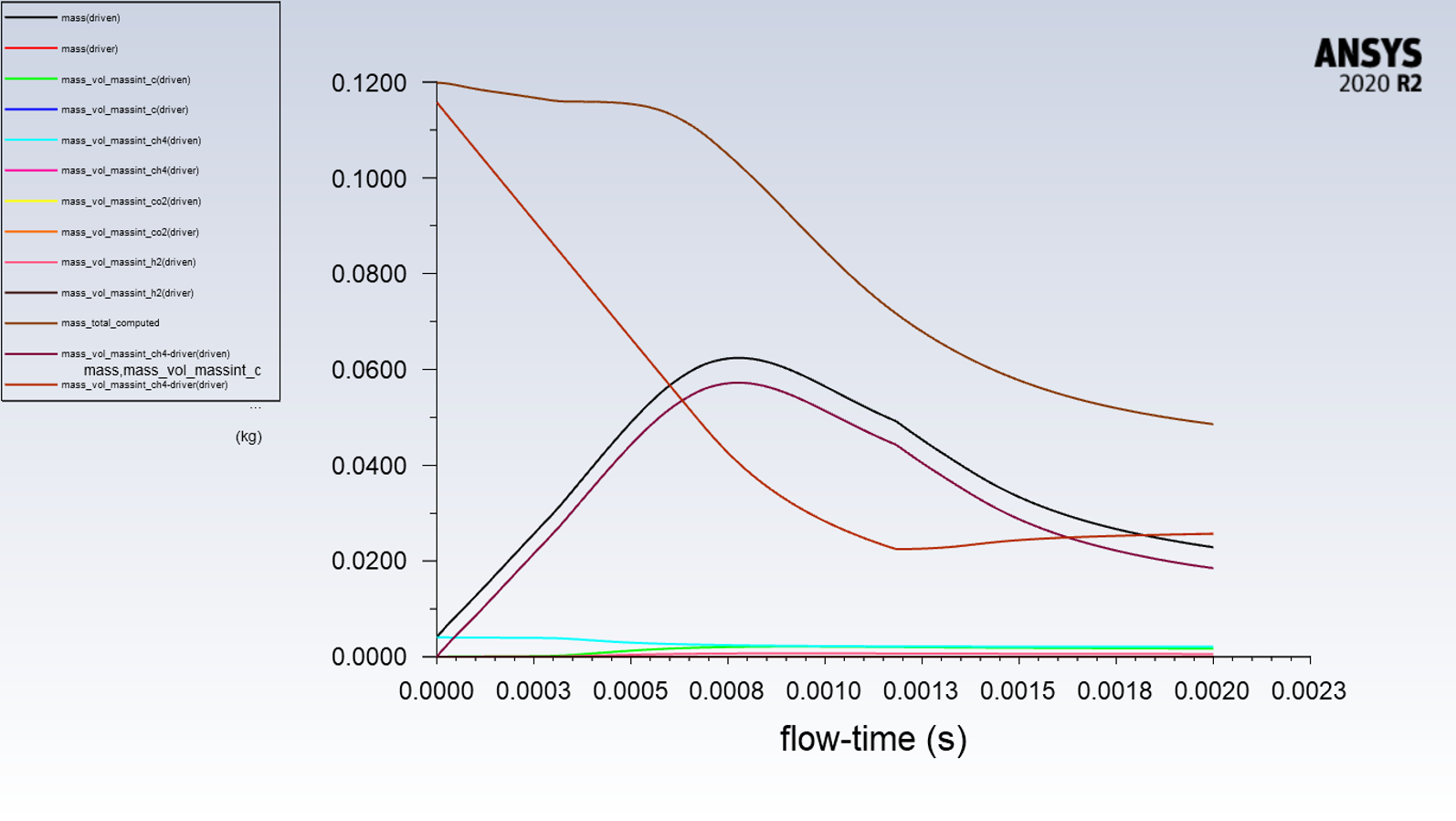
No mass imbalance appears in the CH₄ case as well as with reactions turned off, and it seemed to resolve the mass issue.
However, I conducted a test defining CH₄ as the gas on both the driver and driven sides (same properties but different names), with reactions activated only for CH₄ on the driven side. In this case, a drop in mass was observed.CH4_driver and a CH4_driven
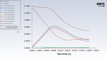
d) What Mach numbers are anticipated in the simulation? Could you also share the residual plots for either the H₂ or CO₂ case?
Theorically, we are xpected Mach numbers approximately 2.5 for CO₂ and 5.5 for H₂. (Attached are the residual plots.)
e) Could we attempt using a segregated solver with first-order (FO) schemes to assess any potential improvement in results?
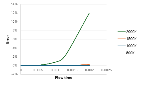
I tested PISO, SIMPLE, and coupled schemes with CO₂ as the driver and CH₄ as the driven gas, using both first and second-order schemes. There are still drcomparison indicated no significant differences. I also experimented with inviscid models, applying no shear stress at the walls.I tested various temperatures for the driver (CO2): 500, 1000, 1500, and 2000K. The results presented in the figure below( mass error over time) show an increase with higher temperatures, which suggests that the chemistry solver might be the issue.
Ghislain
-
October 28, 2024 at 5:30 am
vinaraya
Ansys EmployeeHi,
Could you reshare the first two figures as I cannot see the legends and vertical axis title (it is blurred).
-
October 28, 2024 at 8:37 am
-
October 31, 2024 at 8:41 pm
vinaraya
Ansys EmployeeHi,
Thanks for sharing the updated figures.
a) Since the mass is not getting balanced - i'm suspecting it is mainly to do with the density calculation [Since your volume is constant (being a closed system)]. Could you share the density/pressure/temperature contours for any one of the case (at the begining, intermediate point before the mass imbalance starts to appear and the final contour at the point you stopped)
b) What was the choice of last species used in all your simulations ?
-
November 4, 2024 at 10:38 am
ghislain_madiot
SubscriberHi,
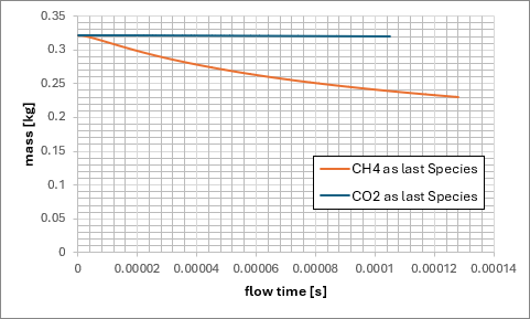
I conducted a test using CO2 as the driver gas, with CH4 and CO2 as the final species. I had to stop the extraction simulation when the mass error reached 0.4% and continued to increase after just 100 iterations, though at a slower rate compared to when CH4 was the last species.
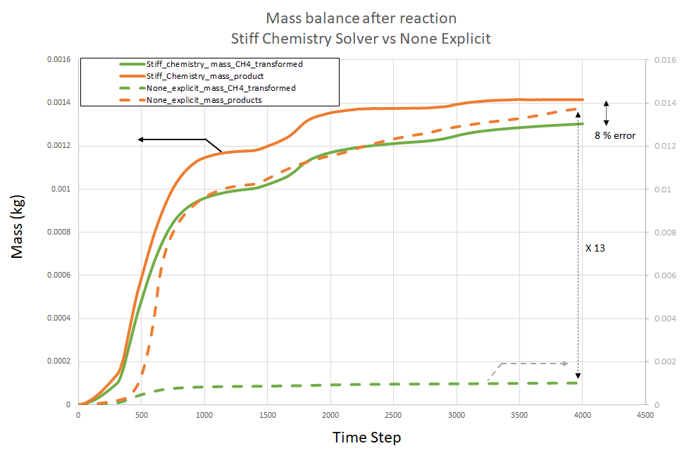
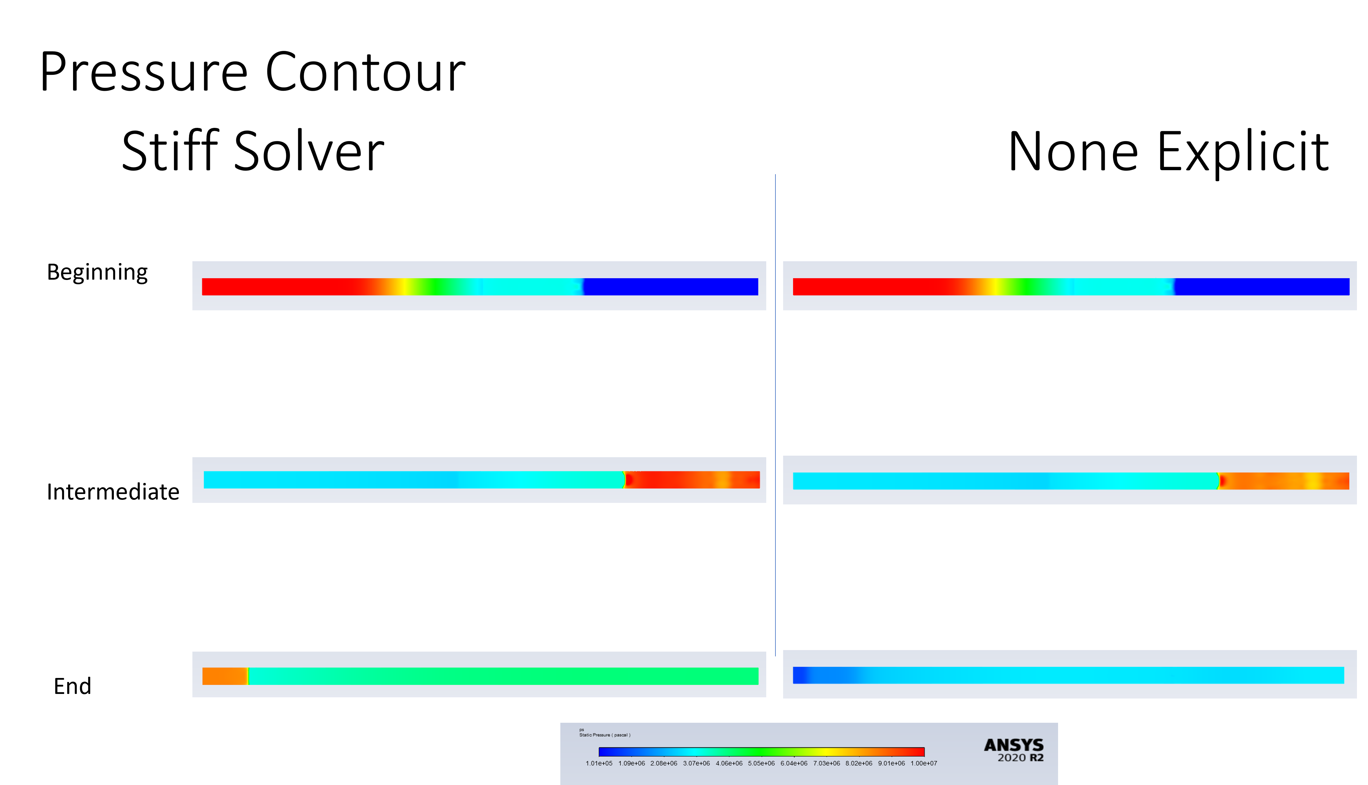
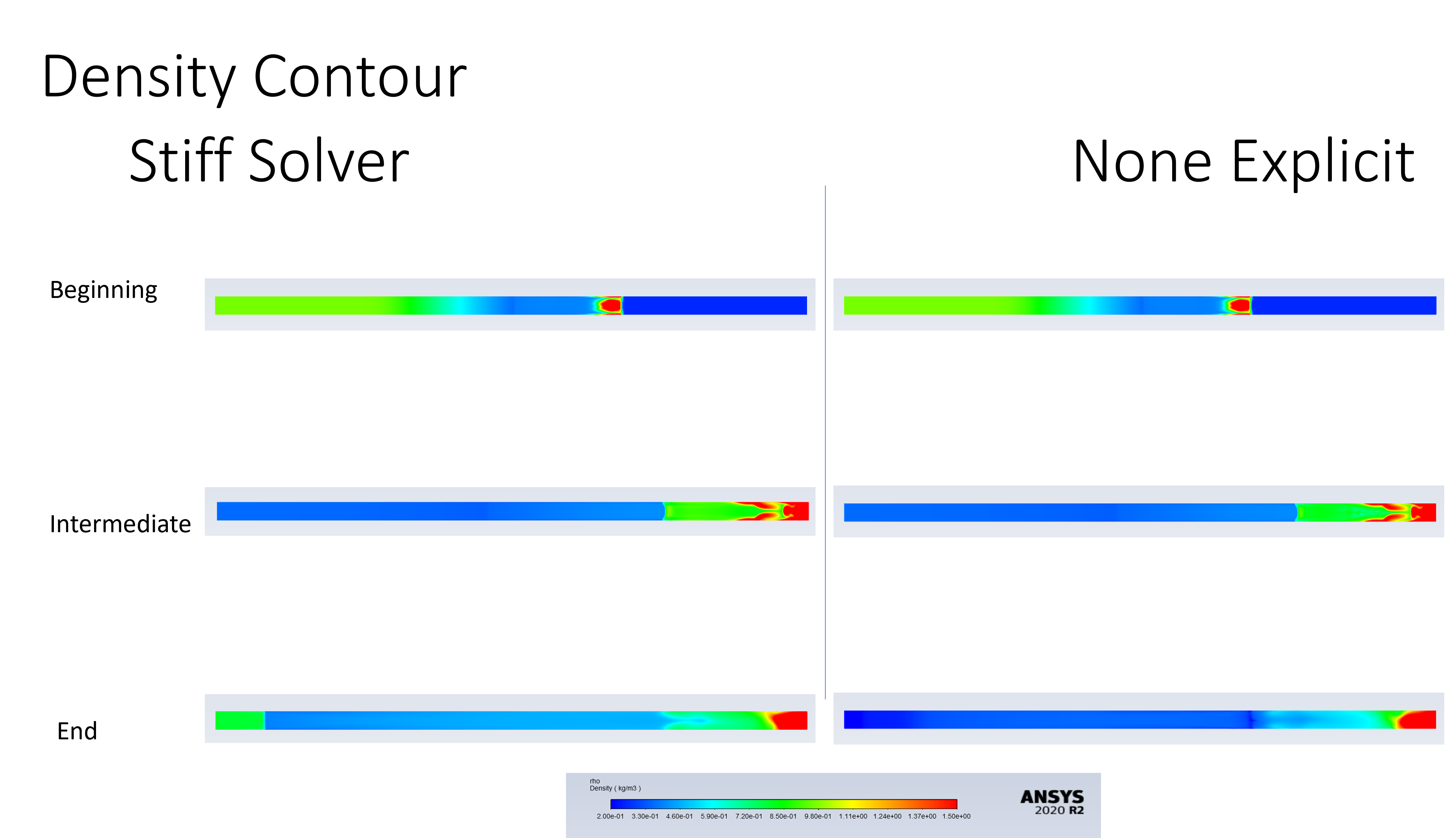
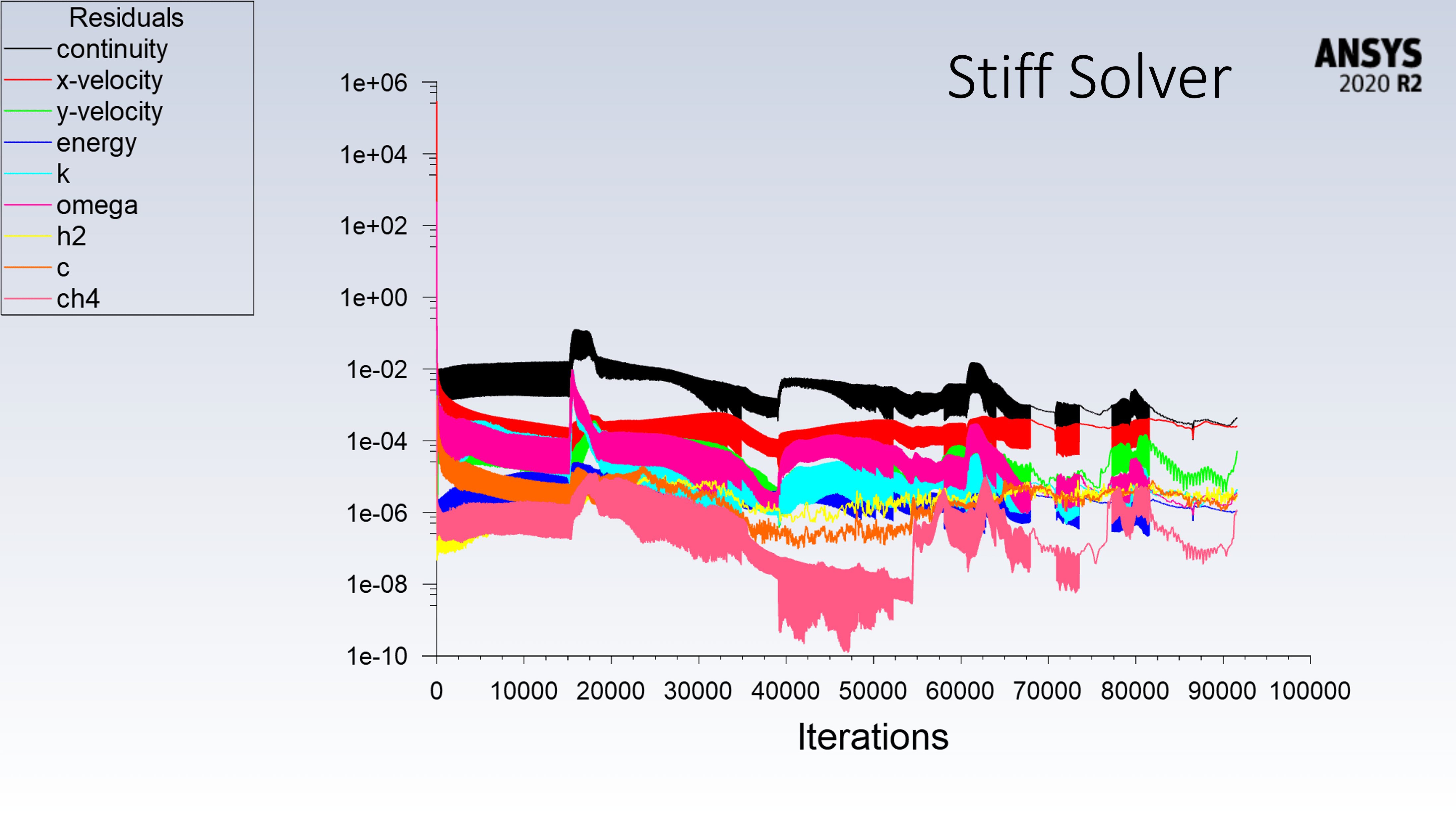
I also compared another chemistry solver, Stiff Chemistry, with the Non-Explicit method using H2 as the driver gas, as this sceanrio has previously shown the most significant error.
I've attached contour plots for density, temperature, and pressure, as well as the residuals for these simulations.
The new solver notably reduced the mass balance error to just 0.05%, indicating that mass conservation is now satisfactory. However, in terms of mass conservation through the reactions, the non-explicit method still shows considerable deviation. While Stiff Chemistry performs better, there's still an 8% discrepancy between the mass of CH4 produced and the (carbon – H2 created)
-
November 11, 2024 at 10:21 am
ghislain_madiot
SubscriberHi Vijay,
Is there anything else you need from me to investigate the mass conservation issue in the methane pyrolysis shock tube simulation? I believe I've provided all the additional analysis you requested.
Also, do you have any recommendations for the chemistry model that would be best suited for this simulation? I'm finding it puzzling that, with identical numerical parameters, one model appears stable while another does not. Any insights on why this could be happening?
Thanks!
-
- You must be logged in to reply to this topic.


-
4638
-
1540
-
1386
-
1225
-
1021

© 2025 Copyright ANSYS, Inc. All rights reserved.


