-
-
May 19, 2022 at 10:04 am
LaraDlg
SubscriberHi,
I have two shells (with constant thickness defined in ansys) , one of the shell is around the first one but they are 1mm apart at the beginning.
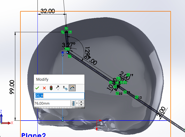
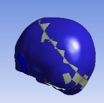
The inner shell has an opening with springs to deform it (the location of this opening would be changed in the DoE) and the aim of the simulation is to assess how the inner shell deforms with the restriction of the outer and softer shell. Imagine a skull expanding under the scalp.
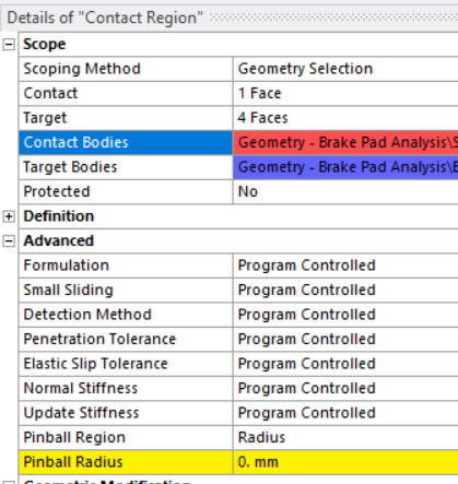
So right now, the software makes me select every faces of each shells manually because they are not in contact yet. I have selected Frictional contact and because the shells have manually defined thicknesses, only the top and bottom faces are selected.
However, when I try to run a DoE, the software looses the manually defined contact because the opening in the shell changes and therefore the faces selected change as well.
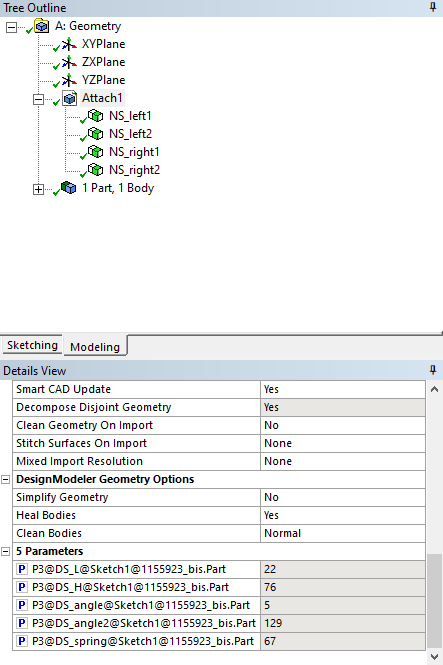
I tried to define each shell as a named selection but the contact tool won't let me select them.
Does anyone know what I'm doing wrong or if there is a solution for this problem at all?
Thank you!
May 19, 2022 at 12:06 pmMay 19, 2022 at 12:31 pmpeteroznewman
SubscriberWhat is the geometry editor that is changing the location of the hole? Is it SpaceClaim or DesignModeler or some other CAD program?
I recommend DesignModeler for DOEs that include geometry parameters.
May 19, 2022 at 12:51 pmLaraDlg
Subscriberthe parameters are selected in DesignModeler but they are created in the geometry in Solidworks because I work with NURBBS files
May 19, 2022 at 2:59 pmpeteroznewman
SubscriberDid you bring the geometry from Solidworks into DM as a Parasolid file?
Then in DM you created parameters to move the hole? What DM feature is used to move the hole?
May 19, 2022 at 3:02 pmLaraDlg
Subscriber
Thanks for your suggestion, I've tried it but unfortunately it's still not working, the warnings ask for user input
May 19, 2022 at 3:05 pmLaraDlg
SubscriberI used the existing link between Solidworks and Ansys: the parameters and the cuts are made in Solidworks (defined as "DS_example") and then the shells are imported as "geometry" and the parameters that I want to use later are selected in DM
May 20, 2022 at 2:21 ampeteroznewman
SubscriberIf you are using the Solidwork-Ansys Geometry Interface correctly, there is no need to use DM. The parameters should be defined in Solidworks and show up in Mechanical as CAD parameters with a DS_ prefix. Please insert some image in your reply to show exactly what you did in Solidwork and Mechanical.
May 20, 2022 at 8:45 amLaraDlg
SubscriberHere is the solidworks picture with the parameter definition and then the selection in DM. I've performed some DoE for this study before and it worked well but it's the first time I try to include manually defined contact. The outer shell is imported as a geometry from solidworks as well but without any parameter and it seems like this shell is the problem because it disappears (the BC for this second shell are lost). Maybe I should try to import them together from solidworks but they both have different material properties and thicknesses.
May 20, 2022 at 9:35 amErik Kostson
Ansys Employee
See if this post helps for the issue of getting in both solid and shell parts from a cad import.
Erik
May 20, 2022 at 9:56 amLaraDlg
SubscriberErik
Thank you for sharing this! Do you think this could be the origin of the contact problem?
May 20, 2022 at 10:01 amErik Kostson
Ansys EmployeeHi
Not sure I am afraid - but something perhaps worth testing especially if you have surfaces/shells imported.
let us know how it goes
Erik
May 20, 2022 at 10:51 amLaraDlg
SubscriberI tried to assemble both shells in Solidworks to import them in one go instead of creating 2 geometries and two mechanical models but even after modifying the properties like in the post you sent, the parameters don't appear anywhere (not even in DM where they use to be). I'm guessing the issue comes from both surfaces being imported together (the import check sign appears in yellow instead of green in DM)
Lara
May 20, 2022 at 12:19 pmViewing 13 reply threads- The topic ‘Manual contact region for Design of Experiment?’ is closed to new replies.
Ansys Innovation SpaceTrending discussionsTop Contributors-
3034
-
971
-
858
-
851
-
792
Top Rated Tags© 2025 Copyright ANSYS, Inc. All rights reserved.
Ansys does not support the usage of unauthorized Ansys software. Please visit www.ansys.com to obtain an official distribution.
-

Ansys Assistant

Welcome to Ansys Assistant!
An AI-based virtual assistant for active Ansys Academic Customers. Please login using your university issued email address.

Hey there, you are quite inquisitive! You have hit your hourly question limit. Please retry after '10' minutes. For questions, please reach out to ansyslearn@ansys.com.
RETRY